Compensation of temperature-induced dispersion drift in optical communication links

a technology of temperature-induced dispersion drift and optical communication link, which is applied in electromagnetic transmission, electrical equipment, transmission, etc., can solve the problems of net dispersion drift at the receiver, the change of the dispersion of the optical plant fiber in the ground (or in the air), and the net dispersion drift across each span as well as at the receiver. , to achieve the effect of reducing the distortion margin in the optical link budget, reducing the net dispersion drift affecting the optical

Inactive Publication Date: 2007-09-25
RPX CLEARINGHOUSE
View PDF2 Cites 8 Cited by
  • Summary
  • Abstract
  • Description
  • Claims
  • Application Information

AI Technical Summary

Benefits of technology

[0006]The present invention recognizes the value of compensating for temperature-induced dispersion drift experienced by an optical signal as it travels along a span of plant fiber. Accordingly, a dispersive effect applied by a dispersion compensator is controlled as a function of temperature data associated with the span, in order to reduce the net dispers

Problems solved by technology

Dispersion is the tendency for different optical wavelength components of an optical signal to propagate at different speeds, leading to distortion at the receivers.
Because conventional technology is static, i.e., the dispersion of each DSCM is fixed, a problem arises when the dispersion of the optical plant fiber in the ground (or in the air) changes due to daily or se

Method used


Image

  • Compensation of temperature-induced dispersion drift in optical communication links
  • Compensation of temperature-induced dispersion drift in optical communication links
  • Compensation of temperature-induced dispersion drift in optical communication links

Examples


Embodiment Construction

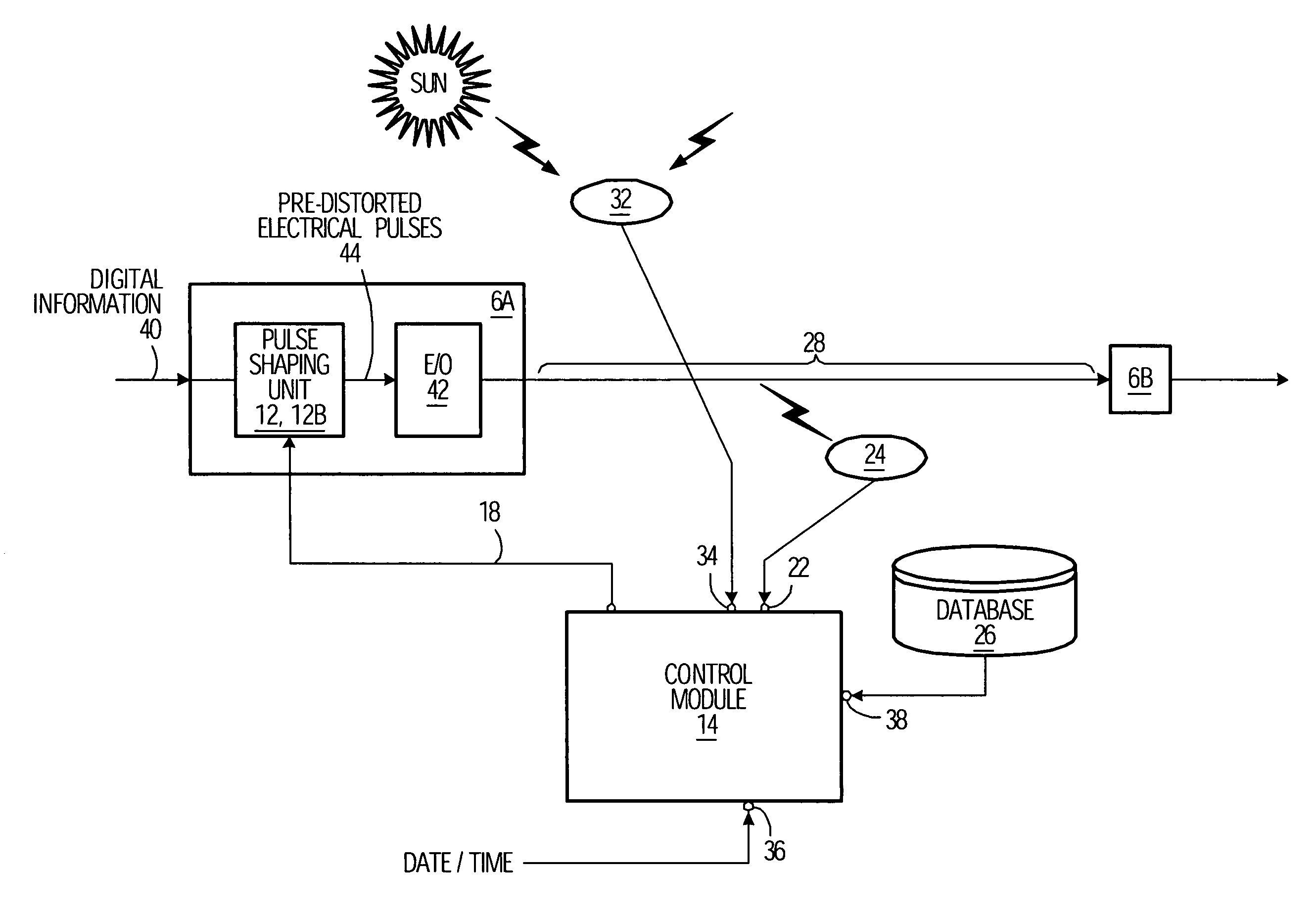
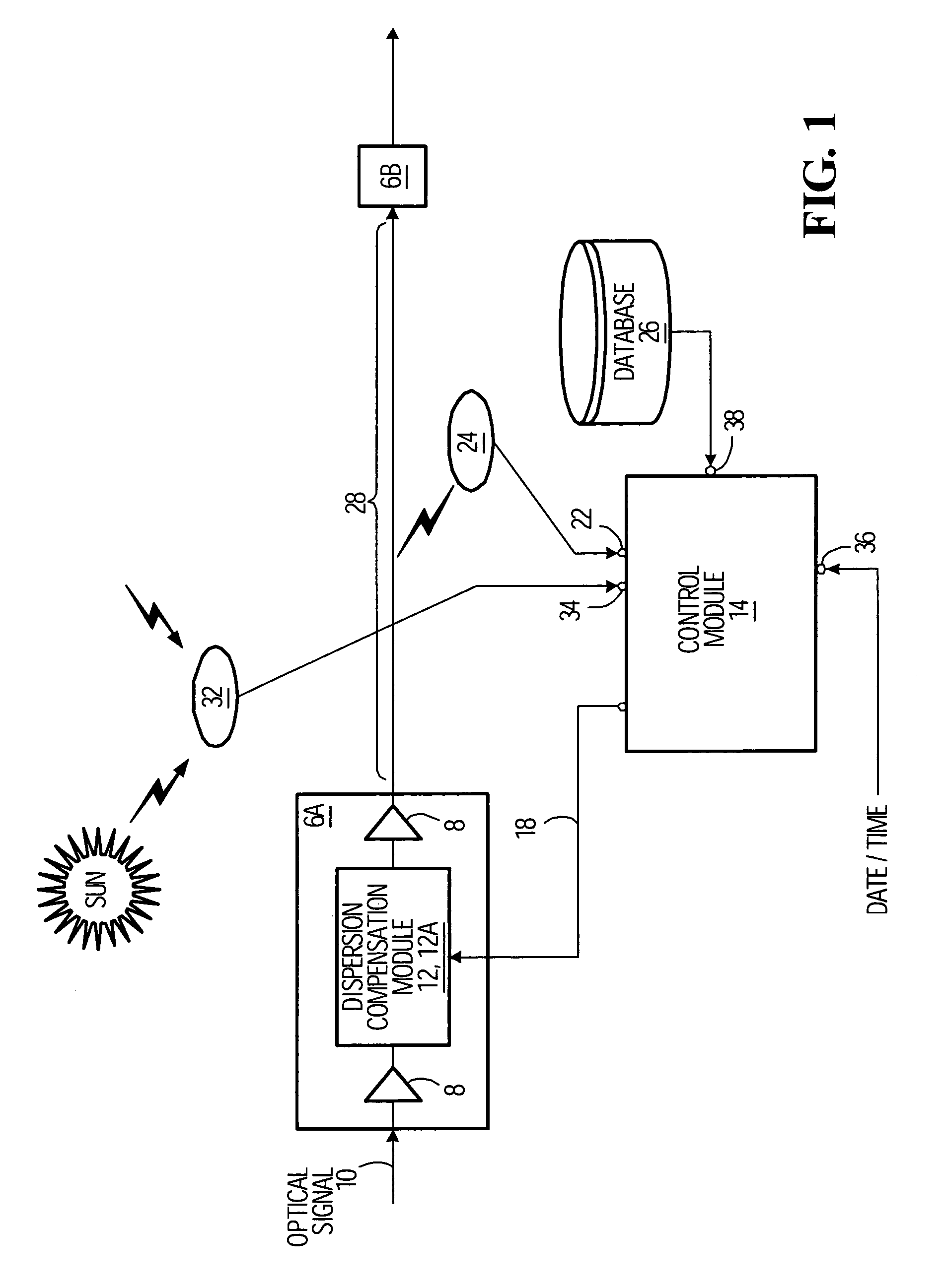
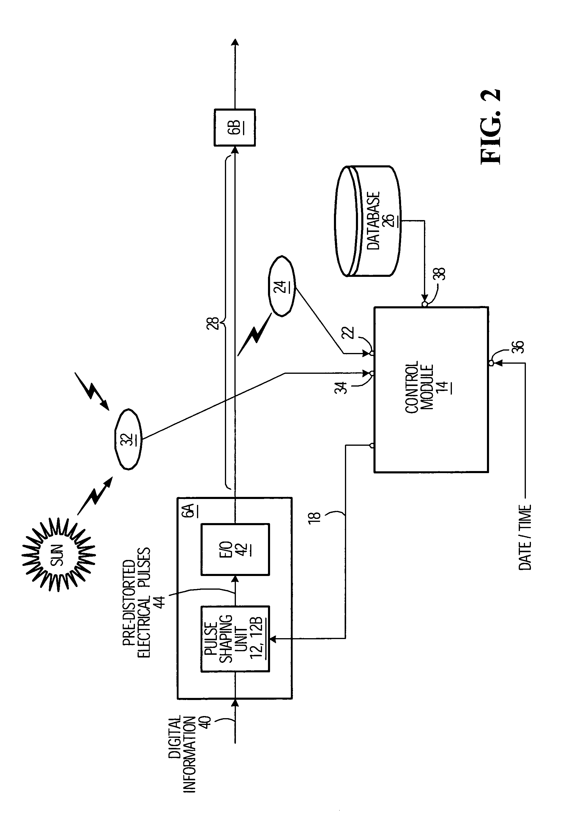
[0018]The dispersion experienced by an optical signal as it travels along an optical path (e.g., a span of optical fiber) is a quantity that is normally expressed in units of picoseconds per nanometer (ps / nm) and which is itself a function of the wavelength, denoted λ.

[0019]Mathematically, the dispersion is the derivative of the group delay with respect to wavelength which, when plotted against wavelength, results in a curve that may be nonlinear. Moreover, it has been observed that the dispersion of an optical signal, at wavelength λ, also varies with both the temperature of the fiber (denoted TF) and the length of the fiber (denoted LF) through which the optical signal propagates. For the sake of notational convenience, the dispersion at wavelength λ experienced by an optical signal that travels an optical path when the latter has a temperature TF is hereinafter denoted DF(λ; TF). In practice, it has been observed that DF(λ; TF) can usually be expressed as:

DF(λ;TF)=(dF*LF)+(KF*LF*...


PUM


Abstract

A control system for use in compensating for temperature-induced dispersion drift of an optical path, comprising an input adapted to obtain temperature data associated with the optical path; a control module adapted to determine control information on the basis of the temperature data; and an output adapted to provide a control signal to a dispersion compensator. The control signal is determined such that its receipt by the dispersion compensator causes the latter to induce a dispersive effect in a signal that travels the optical path, the dispersive effect being related to the control information. The ability to compensate for temperature-induced dispersion drift reduces the distortion margin in optical link budgets, allowing optical links to have longer reach, or to achieve the same reach using fewer line amplifiers. In a specific embodiment, dispersion compensation is accomplished via an open-loop control system such that feedback from the receiver site is not required.

Description

FIELD OF THE INVENTION[0001]The present invention relates generally to optical transmission systems and, more particularly, to control systems for providing compensation of temperature-induced dispersion drift in optical communication links.BACKGROUND OF THE INVENTION[0002]A wavelength-division mutliplex (WDM) long haul optical network typically consists of a number of co-located transmitters (typically electrical-to-optical converters), a multiplexer to combine multiple wavelengths of light onto the same fiber, spans of buried or aerial plant fiber (each typically 40 to 120 km long), optical amplifier sites at the end of each span, a demultiplexer to separate out the wavelengths, and a set of receivers (typically optical-to-electrical converters).[0003]One property of optical fiber which needs to be managed for high bit rate long haul optical networks is dispersion. Dispersion is the tendency for different optical wavelength components of an optical signal to propagate at different...

Claims


Application Information

Patent Timeline
IPC IPC(8): H04B10/12H04B10/00
CPCH04B10/25133H04B10/25137
Inventor SANDLER, HOWARD MARTINO'SULLIVAN, MAURICE
Owner RPX CLEARINGHOUSE
Why Eureka
Try Eureka