Optical amplifier for amplifying a wavelength division multiplexed (WDM) light including light in different wavelength bands

a technology of optical amplifier and wavelength division multiplexing, which is applied in the direction of optical transmission, line-transmission details, electromagnetic repeaters, etc., can solve the problems of difficult to obtain equal gain over a wide band exceeding 60 nm, waveform distortion, transmitted waveform distorted, etc., and achieve the effect of reducing the probability of nonlinear optical effect in the dispersion compensating fiber

Inactive Publication Date: 2005-09-13
FUJITSU LTD
View PDF24 Cites 8 Cited by
  • Summary
  • Abstract
  • Description
  • Claims
  • Application Information

AI Technical Summary

Benefits of technology

[0018]Accordingly, it is an object of the present invention to provide an optical amplifier and optical communication system of simple construction which can compensate for wavelength dispersion with respect to WDM signal light of a wide band. Furthermore, it is an object of the present invention to provide a wavelength dispersion compensation method which reduces the probability of the occurrence of nonlinear optical effects when transmitting WDM signal light.
[0024]With such a construction, the signal lights of adjacent wavelength bands are respectively input from the respective end portions of the dispersion compensating fiber via different optical multiplexing / demultiplexing devices, and propagated in mutually different directions inside the dispersion compensating fiber. As a result, the situation where signal light of large power is concentrated at a specific portion of the dispersion compensating fiber is avoided, and the propagation directions of the lights of adjacent wavelength bands are opposite. Therefore, the probability of the occurrence of nonlinear optical effects in the dispersion compensating fiber is further reduced.
[0026]With such a construction, in the case where wavelength dispersion for the respective wavelength bands cannot be compensated for by a single wavelength dispersion compensator, a first wavelength dispersion compensator for compensating for wavelength dispersion with a dispersion amount for a previously set wavelength as a reference is provided, and a second wavelength dispersion compensator for separately compensating for the wavelength dispersion which is not completely compensated for by the first wavelength dispersion compensator for each respective wavelength band is provided. In this way, an optical amplifier which can perform wavelength dispersion compensation with respect to the respective wavelength bands is realized with a comparatively simple construction.
[0030]With such a construction, when the wavelength division multiplexed signal light, which is multiply repeated and transmitted by the plurality of optical amplifier repeaters, passes through the optical amplifier repeater of the first construction, the wavelength dispersion characteristics of the optical transmission path are compensated for by one wavelength dispersion compensator. With this wavelength dispersion compensation, the dispersion amount for the previously set wavelength is made a reference, and sufficient dispersion compensation is not performed for all of the respective wave bands. Therefore, when the wavelength division multiplexed signal light passes through the optical amplifier repeater of the second construction, the wavelength dispersion which has not been completely compensated for is separately compensated for each respective wavelength band. As a result, the wavelength dispersion characteristics of the optical transmission path can be compensated for all of the plurality of optical amplifier repeaters. Consequently, since the optical amplifier repeater of the first construction has a simple construction, it is easy to realize an optical communication system incorporating a wavelength dispersion function.
[0032]With such a construction, the lights of adjacent wavelength bands are respectively input from the different end portions of the dispersion compensating fiber and propagated in mutually different directions inside the dispersion compensating fiber. As a result, the situation where signal light of large power is concentrated at a specific portion of the dispersion compensating fiber is avoided, and the propagation directions of the lights of adjacent wavelength bands are opposite. Therefore the probability of the occurrence of the nonlinear optical effect in the dispersion compensating fiber is further reduced.

Problems solved by technology

With typical optical amplifiers, in particular optical fiber amplifiers, it is difficult to obtain an equal gain over a wide band exceeding 60 nm.
However, various problems can occur with an optical communication system which transmits signal light over a wide wavelength band.
In this case, there is a problem that the transmitted waveform becomes distorted if the signal light is transmitted at a high transmission speed.
This distortion is due to the wavelength dispersion characteristics of the optical transmission path.
However, when the time slot approaches the delay difference, the influence of the wavelength dispersion increases so that the waveform becomes distorted.
However, in the case where compensation is performed with a wavelength dispersion of 1.55 μm as a reference, as the wavelength band of the signal light is increased, the compensation error increases as the deviation of the wavelength from 1.55 μm increases.
Therefore, for example, a nonlinear optical effect such as cross-phase modulation (XPM) or four-wave mixing (FWM) is likely to occur, so that there is the likelihood of degradation of the transmission characteristics.

Method used


Image

  • Optical amplifier for amplifying a wavelength division multiplexed (WDM) light including light in different wavelength bands
  • Optical amplifier for amplifying a wavelength division multiplexed (WDM) light including light in different wavelength bands
  • Optical amplifier for amplifying a wavelength division multiplexed (WDM) light including light in different wavelength bands

Examples


Embodiment Construction

[0047]Reference will now be made in detail to the present preferred embodiments of the present invention, examples of which are illustrated in the accompanying drawings, wherein like reference numerals refer to like elements throughout.

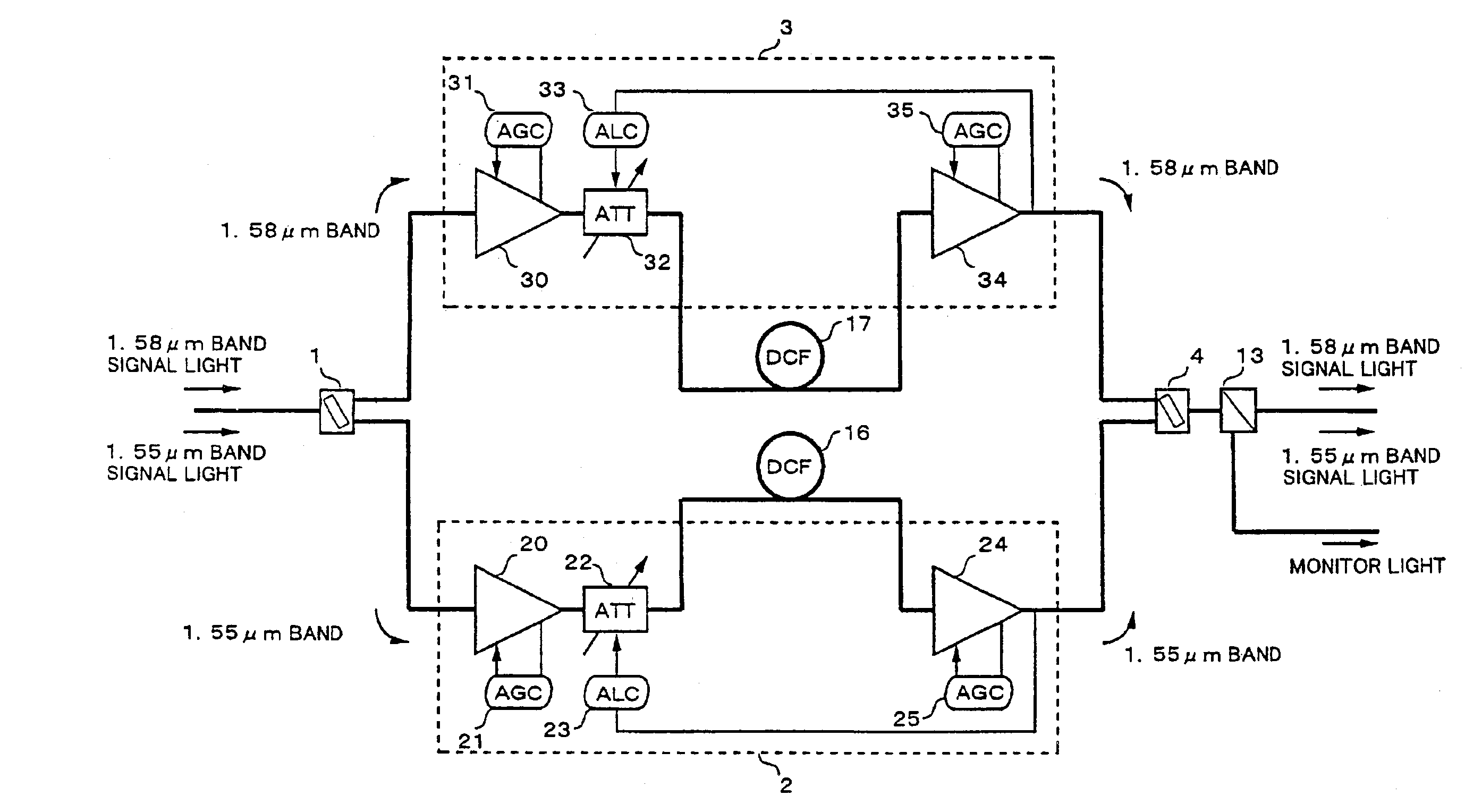
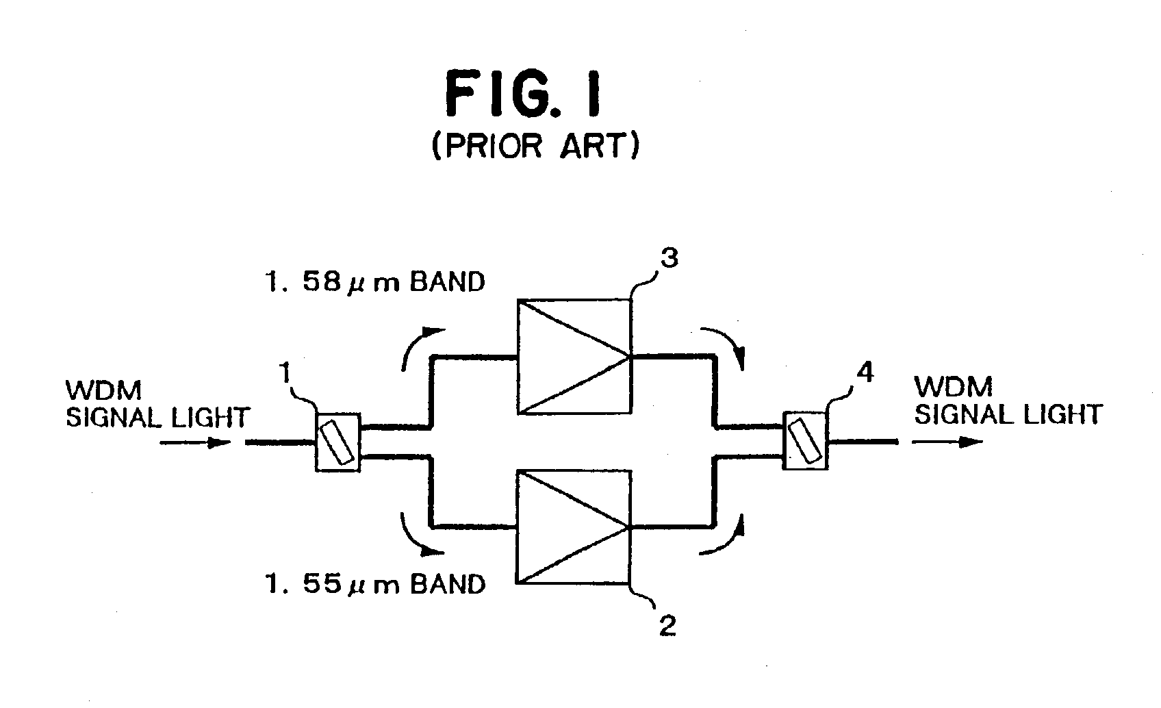
[0048]FIG. 3 is a diagram showing an optical amplifier, according to an embodiment of the present invention. Referring now to FIG. 3, a WDM signal light from, typically, a SMF (not illustrated) includes signal light in a 1.55 μm band and a 1.58 μm band. A WDM coupler 1 demultiplexes the WDM signal light according to the wavelength bands, and the signal light in the 1.55 μm band is sent to a 1.55 μm band optical fiber amplifier section 2, and the signal light in the 1.58 μm band is sent to a 1.58 μm band optical fiber amplifier section 3. As an example, the signal light in the 1.55 μm band might include signal lights of thirty two waves multiplexed in a wavelength band from 1535 nm to 1565 nm. As an example, the signal light in the 1.58 μm band might i...


PUM


Abstract

An optical amplifier, or optical repeater, for amplifying wavelength division multiplexed (WDM) light. A first demultiplexer demultiplexes the WDM light into first and second lights corresponding to different wavelengths in the WDM light. First and second optical amplifiers amplify the first and second lights, respectively. A first multiplexer multiplexes the amplified first and second lights into a multiplexed light. A dispersion compensator compensates for dispersion in the multiplexed light. A second demultiplexer demultiplexes the dispersion compensated, multiplexed light into the first and second lights. Third and fourth optical amplifiers amplify the demultiplexed first and second lights, respectively. A second multiplexer multiplexes the amplified first and second lights from the third and fourth optical amplifiers into a WDM light. The optical amplifier can be configured so that the first and second lights travel through the dispersion compensator in opposite directions.

Description

CROSS-REFERENCE TO RELATED APPLICATIONS[0001]This is a divisional of application Ser. No. 09 / 382,701, filed Aug. 23, 1999, now U.S. Pat. No. 6,768,578.[0002]This application is based on, and claims priority to, Japanese application 10-249658, filed Sep. 3, 1998, in Japan, and which is incorporated herein by reference.BACKGROUND OF THE INVENTION[0003]1. Field of the Invention[0004]The present invention relates to an optical amplifier and optical amplification method for amplifying wavelength division multiplexed (WDM) light which includes light in different wavelength bands.[0005]2. Description of the Related Art[0006]Research and development in the area of wavelength division multiplexed (WDM) optical communication systems has resulted in a steady increase in the number of wavelengths being multiplexed together. In addition, the wavelength bands for transmission are being widened.[0007]Furthermore, research and development is also advancing the development of WDM optical communicati...

Claims


Application Information

Patent Timeline
Patent Type & Authority Patents(United States)
IPC IPC(8): H04B10/18H04B10/17H01S3/06H01S3/067H01S3/131H01S3/094H01S3/23H04B3/04H04B10/07H04B10/2507H04B10/2525H04B10/2557H04B10/2563H04B10/29H04B10/294H04B10/297
CPCH01S3/06758H04B10/25133H04B10/296H04B10/2972H04B10/2941H01S3/06704H01S3/06725H01S3/094011H01S3/2391H04B2210/256H04B2210/258H01S3/1301H01S3/13013H01S3/06766
Inventor KINOSHITA, SUSUMUSUGAYA, YASUSHI
Owner FUJITSU LTD
Why Eureka
Try Eureka