
Movable access points and repeaters for minimizing coverage and capacity constraints in a wireless communications network and a method for using the same

wireless communication technology, applied in the field of mobile access points and repeaters in a wireless communications network for minimizing coverage and capacity constraints in the network, can solve the problems of exacerbated coverage and capacity constraints, inability to deploy numerous base stations in these commuting areas, and inability to provide an adequate number of base stations for a region, etc., to achieve the effect of improving the ability of a wireless communications network

Inactive Publication Date: 2006-12-12
ARRIS ENTERPRISES LLC
View PDF124 Cites 60 Cited by
  • Summary
  • Abstract
  • Description
  • Claims
  • Application Information

AI Technical Summary

Benefits of technology

[0019]An object of the present invention is to provide a system and method for improving the ability of a wireless communications network, such as a packet-switched data communications network, to provide service to mobile user terminals.
[0021]Another object of the present invention is to provide mobile access points for a wireless communications network to minimize the amount of holes in the coverage areas of the network and thus improve service to mobile user terminals accessing the network.

Problems solved by technology

The problem of providing an adequate number of base stations for a region is also exacerbated in areas where heavy commuting traffic occurs.
However, at all other times of the day and on weekends, these stretches of highway may receive only a modest amount of traffic.
Accordingly, it is impractical to deploy numerous base stations in these commuting areas simply to accommodate the few hours of increased activity per weekday.
The number of base stations that can be deployed may also be limited due to space and zoning constraints.
Hence, due to the lack of adequate base stations in these commuting areas, the network may be incapable of adequately servicing its subscribers during these busy commuting hours of the workday.
Other variables, such as the distance between a user terminal and a base station it is trying to access, interference in the base station's coverage area, the existence of structures such as buildings which block the line of sight (LOS) path between a user terminal and a base station, as well as regulatory and site restrictions, also create holes in the coverage areas which adversely affect the capacity capabilities of the network.
Users become aware of such holes because they either lose service or get very poor service in a particular location.
However, these solutions are difficult to deploy because of the size, cost and complexity of traditional base station equipment.
However, in regions such as high traffic commuting regions having an inadequate number of base stations, more user terminals are competing for access to a base station within their coverage area.
Accordingly, the number of lost or dropped calls that may occur during the handoff process can be increased due to the lack of adequate base station accessibility.
Hence, as with traditional cellular communications networks, similar problems can arise in these packet-switched data networks which service mobile user terminals.
That is, these types of networks can also experience an increased occurrence of dropped or lost data communications for mobile user terminals, and the inability of mobile user terminals to adequately access the network, if the number of access points deployed in high traffic areas is inadequate.
However, this patent does not provide any suitable solution for eliminating the problems discussed above relating to holes in the coverage areas of traditional cellular networks or packet-switched data networks.

Method used


Image

  • Movable access points and repeaters for minimizing coverage and capacity constraints in a wireless communications network and a method for using the same
  • Movable access points and repeaters for minimizing coverage and capacity constraints in a wireless communications network and a method for using the same
  • Movable access points and repeaters for minimizing coverage and capacity constraints in a wireless communications network and a method for using the same

Examples


Embodiment Construction

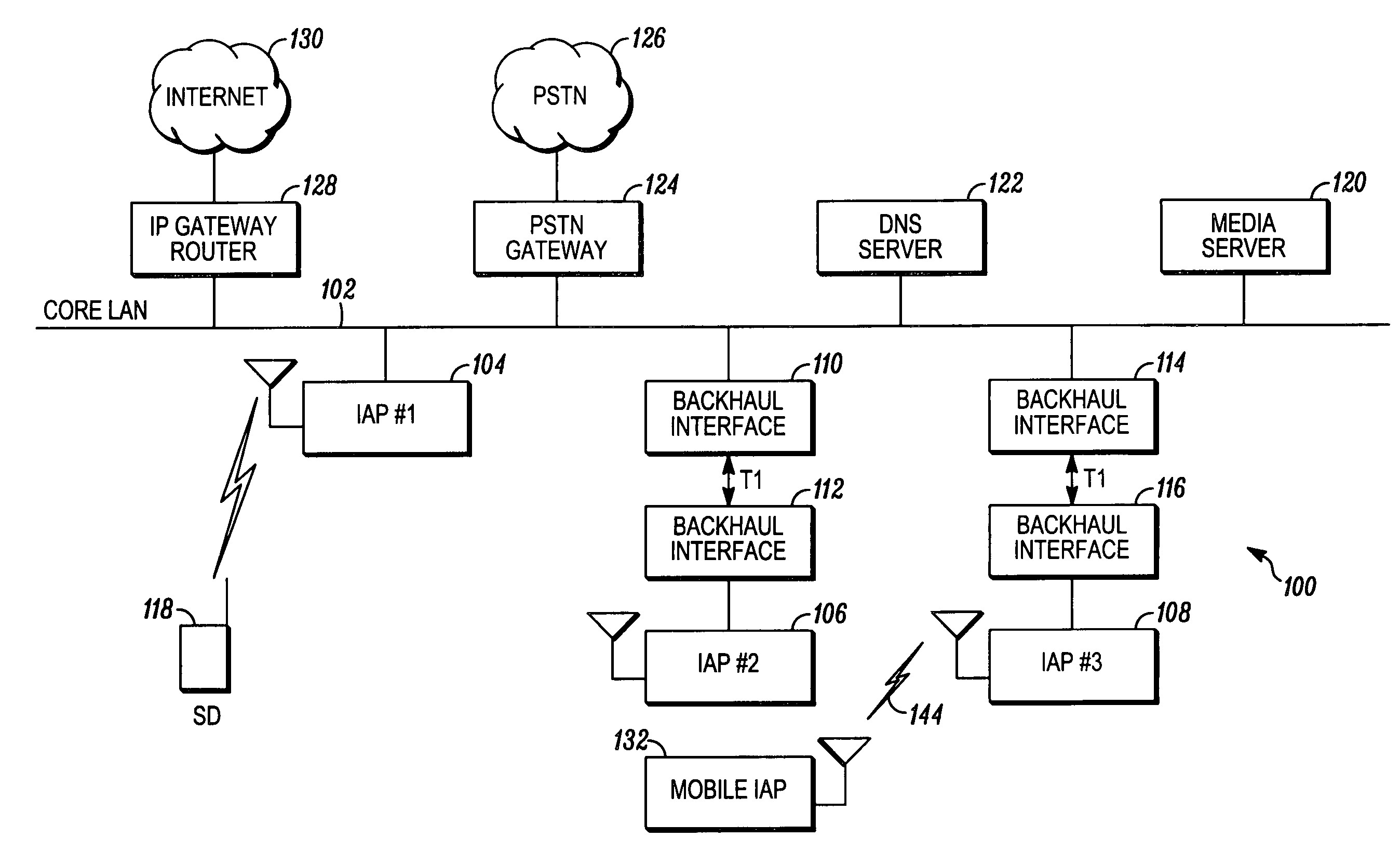
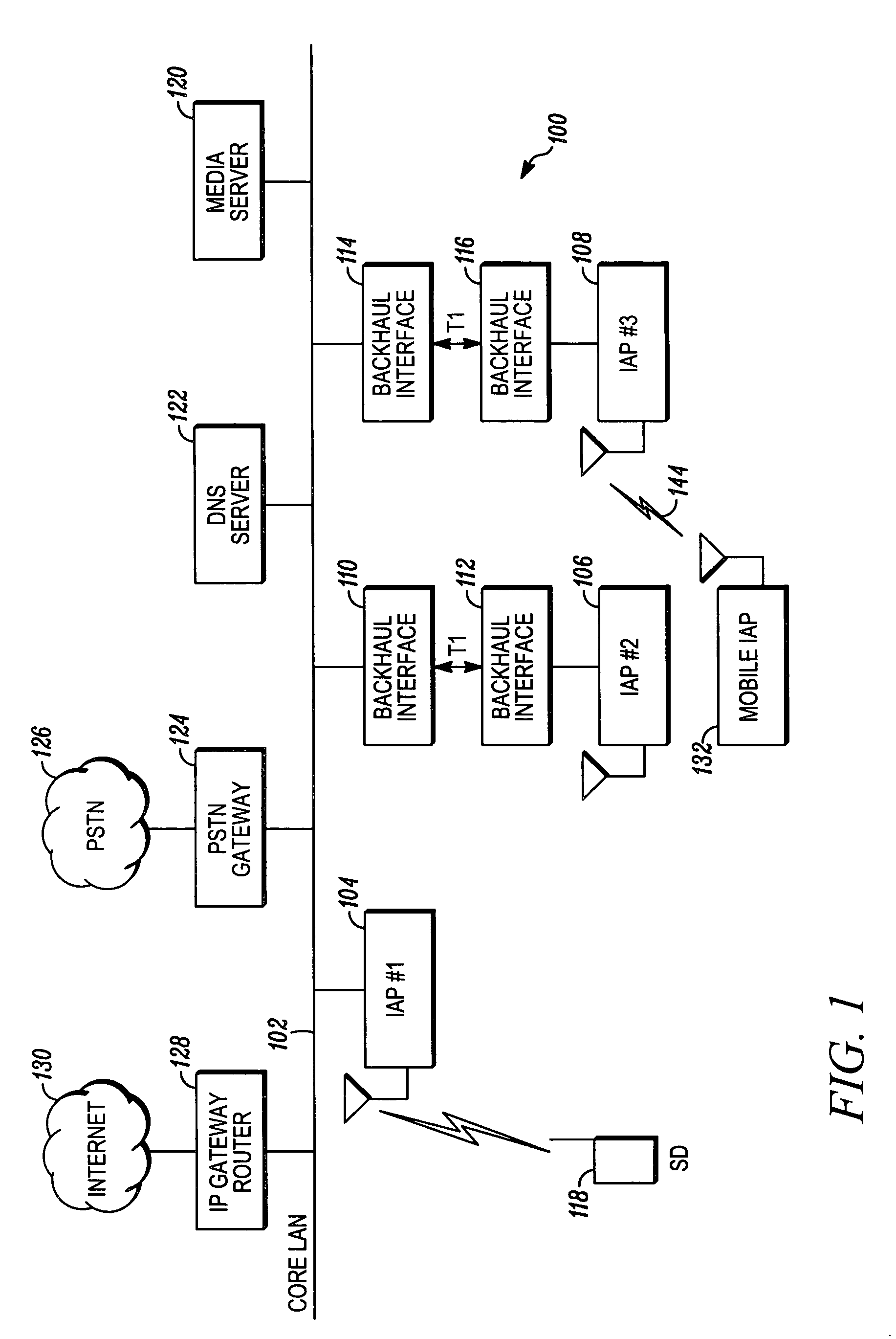
[0030]FIG. 1 is a block diagram illustrating an example of a wireless communications network 100 employing mobile access terminals according to an embodiment of the present invention. As shown, network 100, which can be referred to as a “core network”, includes a core local access network (LAN) 102 which provides the wired infrastructure for the network 100. A plurality of intelligent access points (IAP) 104, 106 and 108 are coupled to and communicate with the core LAN 102. As illustrated in this example, IAP 104 is directly coupled to the core LAN 102, while IAP 106 is coupled to core LAN 102 via backhaul interfaces 110 and 112 and a T1 connection, and IAP 108 is coupled to core LAN 102 via backhaul interfaces 114 and 116 and a T1 connection. However, any suitable backhaul technology, such as T3, fiber and microwave, can be used to implement a number of backhaul modulation techniques in the wireless applications, including QDMA, TDMA, CDMA and FDMA, as pointed out in the Background...


PUM


Abstract

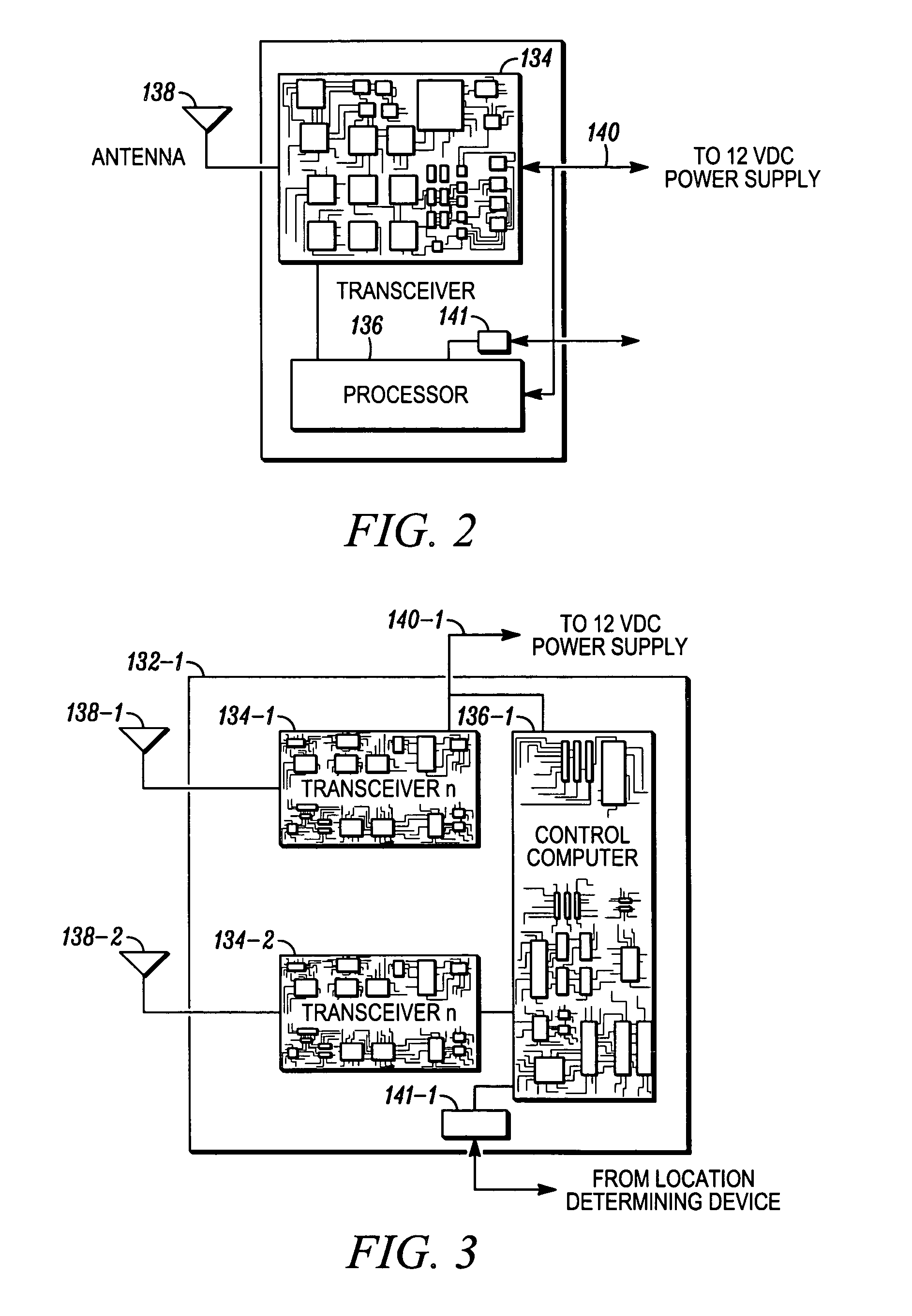
A system and method for improving the ability of a wireless communications network, such as a packet-switched data communications network, to provide service to mobile user terminals. The system and method employs a mobile access point, adapted for use with the packet-switched communications network, to provide a mobile wireless user terminal with access to the network, and a method for using the same. The mobile access point can be mounted to a mobile vehicle and receives substantially constant power from the vehicle, and is adapted to transmit and receive communications signals to and from wireless user terminals, fixed access points and other networks and mobile access points. The mobile access point includes at least one or more transceivers, which allows the access point to support multiple wireless communication protocols. A first protocol may be supported allowing network access, and a second protocol may be used for backhaul service.

Description

[0001]This application is a continuation of application Ser. No. 09 / 929,030, filed Aug. 15, 2001, the entire contents of which being incorporated herein by reference.BACKGROUND OF THE INVENTION[0002]1. Field of the Invention[0003]The present invention relates to movable access points and repeaters in a wireless communications network for minimizing coverage and capacity constraints in the network. More particularly, the present invention relates to constantly moveable access points of a core network of an ad-hoc wireless packet-switched data communications network, which provide user terminals with access to the core network and also are capable of functioning as repeaters between user terminals to enhance the self healing capabilities of the ad-hoc network.[0004]2. Description of the Related Art[0005]Wireless communications networks, such as mobile wireless telephone networks, have become increasingly prevalent over the past decade. These wireless communications networks are common...

Claims


Application Information

Patent Timeline
Patent Type & Authority Patents(United States)
IPC IPC(8): H04Q7/00H04B7/14H04B7/15H04W88/08H04L12/28H04L12/70H04W88/02
CPCH04W88/02H04L2012/5603H04W88/08
Inventor GARAHI, MASOODSTANFORTH, PETER J.
Owner ARRIS ENTERPRISES LLC
Learn More