Subterranean equipment bay

a technology for subterranean equipment and equipment, which is applied in the direction of cable installation in the cable chamber, electric cable installation, electric cable installation, etc., can solve the problems of uncharted or imprecise location of telecommunications equipment, many challenges in the underground housing of telecommunications equipment, and increase the difficulty of excavating such a deep hole. achieve the effect of reducing the visual impact of the aboveground placement and reducing the problems associated

Inactive Publication Date: 2006-12-12
SPRING SPECTRUM LP
View PDF14 Cites 15 Cited by
  • Summary
  • Abstract
  • Description
  • Claims
  • Application Information

AI Technical Summary

Benefits of technology

[0007]The present invention is specifically directed to a subterranean equipment bay useful for housing telecommunications equipment. In an embodiment, the equipment bay is a vault of a shallow depth to reduce problems associated with deep excavation. The equipment bay helps to reduce the visual impact of the aboveground placement of telecommunication equipment components. In addition, the equipment bay may be adapted to house the telecommunication equipment components in an orientation other than the normal, vertical upright position, and is equipped with a ventilation system adequate to ventilate telecommunications equipment components within the bay. The equipment bay may further be equipped with a water drainage system adequate to sufficiently drain excess water infiltration from accumulating within the equipment bay. The equipment bay may be further equipped with means for mounting the telecommunications equipment elevated from the floor of the bay.

Problems solved by technology

Housing the telecommunications equipment underground presents many challenges.
Excavating such a deep hole presents further hazards.
Despite best efforts to determine the location of these potential hazards, their location is often uncharted or imprecise.
Severing one of these wires or lines may create hazardous conditions, as well as require the vault to be moved to a different location.
This may result in undesirable delays and increased installation costs.
Moreover, deep excavations often require shoring of the sidewalls to prevent collapse during vault installation, adding further complexities and costs.

Method used


Image

  • Subterranean equipment bay
  • Subterranean equipment bay
  • Subterranean equipment bay

Examples


Embodiment Construction

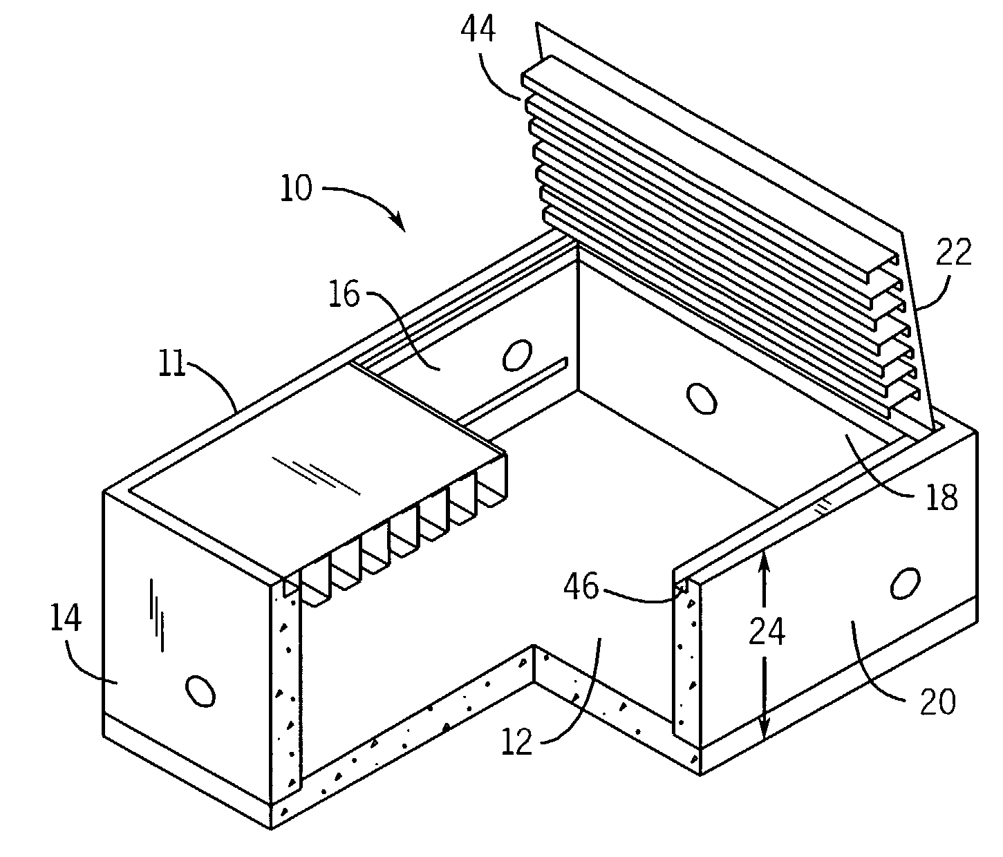
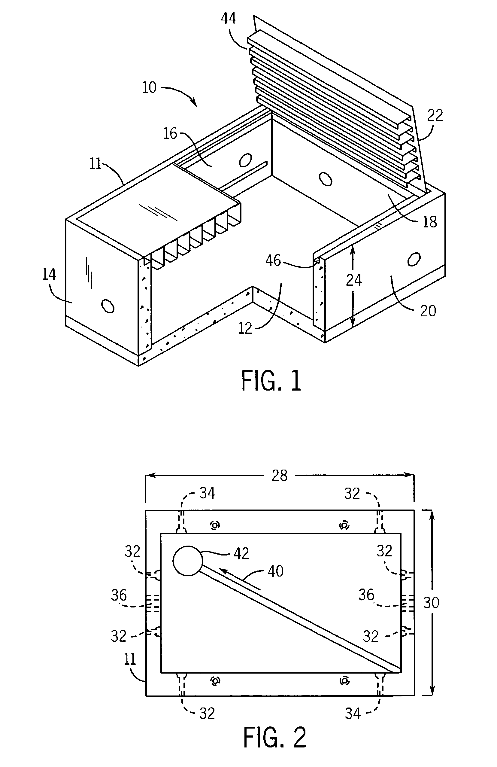
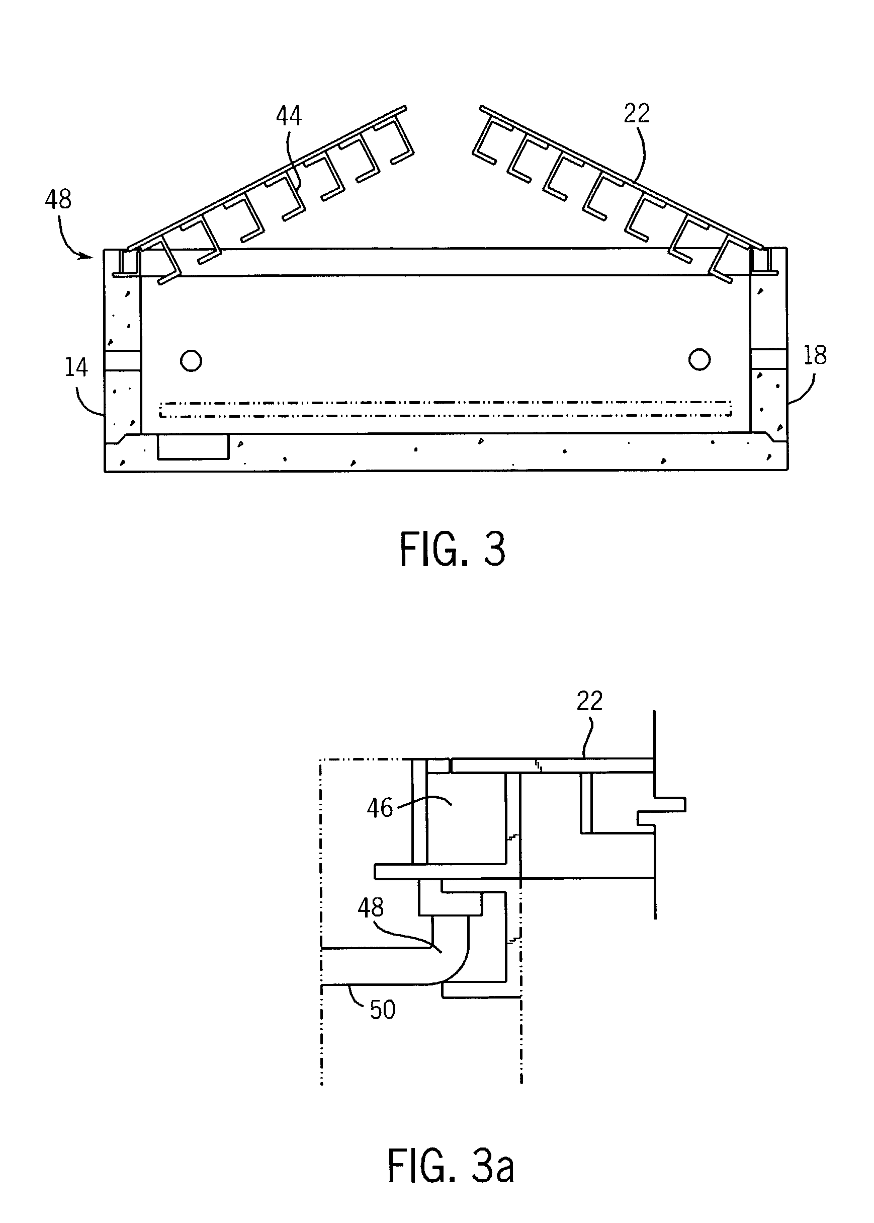
[0022]With reference to FIG. 1, an illustrative subterranean equipment bay 10 is shown. Equipment bay 10 is comprised of a vault 11 that includes a base 12, and a first sidewall 14, a second sidewall 16, a third sidewall 18, and a fourth sidewall 20. Sidewalls 14, 16, 18, and 20 extend upwardly from base 12. Vault 11 further includes a top cover 22 positioned opposite the base 12. Vault 11 is preferably made of concrete and is suitable for placement underground such that the top cover 22 is positioned at ground level and the rest of the vault is underground. Equipment bay 10 is preferably placed on a minimum of a six-inch deep crusher run rock base for ease of installation and even load distribution. The base 12 is preferably comprised of a six-inch thick base slab of concrete.

[0023]In order to minimize the depth of excavation required for installation of the vault 11, the vault preferably has a depth 24 that is three feet or less. With this shallow depth, the excavation required is...


PUM


Abstract

A subterranean equipment bay for housing telecommunications equipment comprising a vault having a floor, sidewalls, and a top cover, and having a shallow depth. The vault further includes means for ventilating the vault and means for removing water from the vault.

Description

BACKGROUND OF INVENTION[0001]1. Field of Invention[0002]The present invention is directed to a telecommunications equipment bay, and more particularly to a subterranean equipment bay suitable for housing telecommunications equipment.[0003]2. Background of the Invention[0004]To support a nationwide network for wireless communication, a series of base stations or cells housing telecommunications equipment are positioned across the country. A cell may be located in or near population centers to provide service to the local population. A typical base station may include CDMA Distributed Base Station Equipment consisting of a Radio Frequency Unit (RFU), a Base Band Unit (BBU), as well as a Power Backup Cabinet (PBC), and is well suited for covering urban and rural trouble spots, office parks, tunnels, subways, and malls. The equipment is normally located above-ground, often positioned on utility poles, and the equipment components are designed to be installed in a vertical upright positi...

Claims


Application Information

Patent Timeline
Patent Type & Authority Patents(United States)
IPC IPC(8): H04B1/38H04M1/00
CPCH02G9/10
Inventor HOLLEN, TIMOTHY
Owner SPRING SPECTRUM LP
Why Eureka
Try Eureka