Method and apparatus for impedance signal localizations from implanted devices

a technology of impedance signal and localization method, which is applied in the field of implantable medical devices, can solve problems such as problems such as problems such as problems such as the difficulty of measuring changes in impedance or resistivity in a certain contributing factor

Active Publication Date: 2006-12-12
MEDTRONIC INC
View PDF20 Cites 95 Cited by
  • Summary
  • Abstract
  • Description
  • Claims
  • Application Information

AI Technical Summary

Problems solved by technology

Measuring changes in impedance or resistivity in a certain contributing factor can be problematic, since such changes tend to be relatively accurately detectable across one vector while being less susceptible to accurate detection across another vector.

Method used


Image

  • Method and apparatus for impedance signal localizations from implanted devices
  • Method and apparatus for impedance signal localizations from implanted devices
  • Method and apparatus for impedance signal localizations from implanted devices

Examples


Embodiment Construction

[0021]The following detailed description should be read with reference to the drawings, in which like elements in different drawings are numbered identically. The drawings, which are not necessarily to scale, depict selected embodiments and are not intended to limit the scope of the invention. Several forms of invention have been shown and described, and other forms will now be apparent to those skilled in art. It will be understood that embodiments shown in drawings and described above are merely for illustrative purposes, and are not intended to limit scope of the invention as defined in the claims that follow.

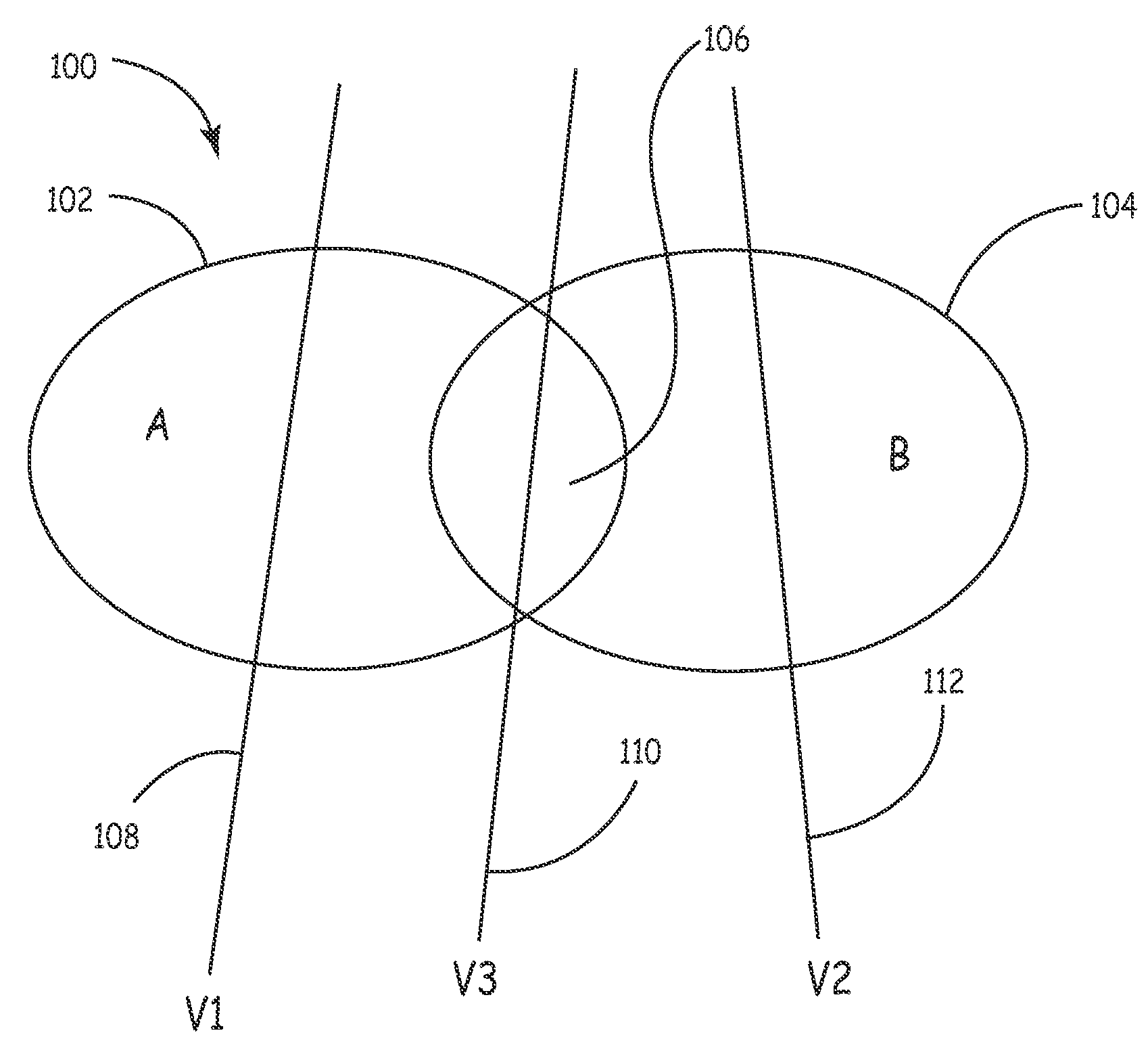
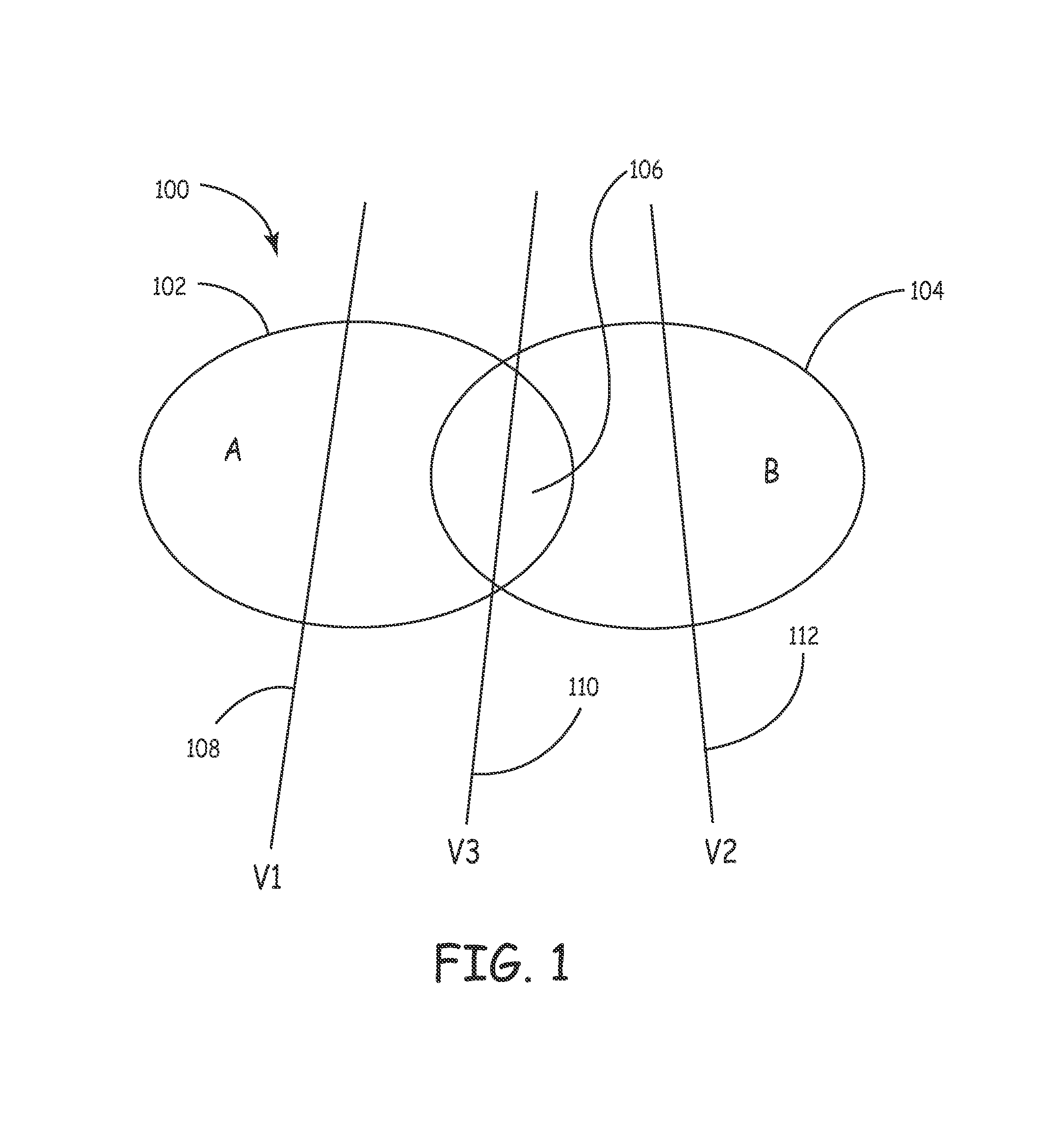
[0022]FIG. 1 is a schematic diagram of impedance vectors crossing physiological impedance change factors. As illustrated in FIG. 1, an abstract diagram 100 illustrating a simplified example of the present invention includes one physiological factor contributing to changes in impedance over time as sensed across various vectors, Factor A, and another physiological factor cont...


PUM


Abstract

A patient monitoring system including an implantable medical device for monitoring a plurality of physiological factors contributing to physiological conditions of a patient's heart by measuring a first impedance affected by the plurality of physiological factors, across one of a plurality of vectors, and a second impedance affected by the plurality of physiological factors, across a second one of the plurality of vectors subsequent to determining the first impedance. A change in impedance is determined based upon the first impedance and the second impedance measurements. Using an equation ΔZVX=αAVX*QA+αBVX*QB, where QA is a fractional resistivity change of a first contributing physiological impedance factor, QB is a fractional resistivity change of a second physiological impedance factor, αAVX is an impedance sensitivity factor for physiological impedance factor QA, and αBVX is an impedance sensitivity factor for physiological impedance factor QB, the value of one of the contributing physiological impedance factors is determined. The contributing physiological impedance factors may include lung resistivity, blood resistivity, heart muscle resistivity, skeletal muscle resistivity, heart volume and lung volume.

Description

FIELD OF THE INVENTION[0001]The present invention relates generally to implantable medical devices (IMDs), and more particularly, the present invention relates to an apparatus and method for identifying cardiac insult using comparisons of multiple impedance vectors to differentiate between the physiological factors that contribute to cardiac insult.BACKGROUND OF THE INVENTION[0002]The impedance measuring vectors or paths provided by some modern pacemakers and implantable cardio defibrillators are quite extensive. Many pacemakers currently measure impedance to measure minute ventilation as a physiological indicator of activity. The minute ventilation value obtained in this way can be used to set the pacing rate in a physiological adaptive pacemaker. The impedance changes over time over a particular vector can have many contributing factors, some major and some minor, so that multiple factors contribute to impedance signals measured by the device. A nonexclusive list of such contribut...

Claims


Application Information

Patent Timeline
Patent Type & Authority Patents(United States)
IPC IPC(8): A61B5/05A61B5/053A61B5/08A61N1/365
CPCA61B5/053A61N1/36521A61B5/0809A61B5/7285
Inventor WANG, LI
Owner MEDTRONIC INC
Why Eureka
Try Eureka