

Method and device for determining the peep during the respiration of a patient
a technology for respiration and peep, which is applied in the direction of valve operating means/releasing devices, applications, diagnostic recording/measuring, etc., can solve the problems of damage to and function restrictions of brain, liver, kidneys, etc., and achieve the effect of reducing the peep and lowering the peep
- Summary
- Abstract
- Description
- Claims
- Application Information
AI Technical Summary
Benefits of technology
Problems solved by technology
Method used
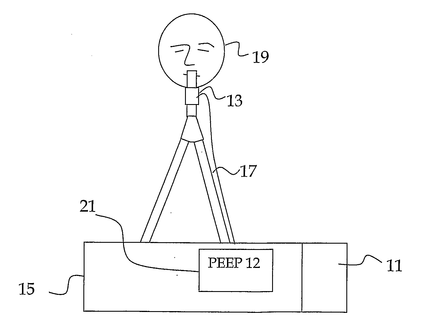
Image

Examples
Embodiment Construction
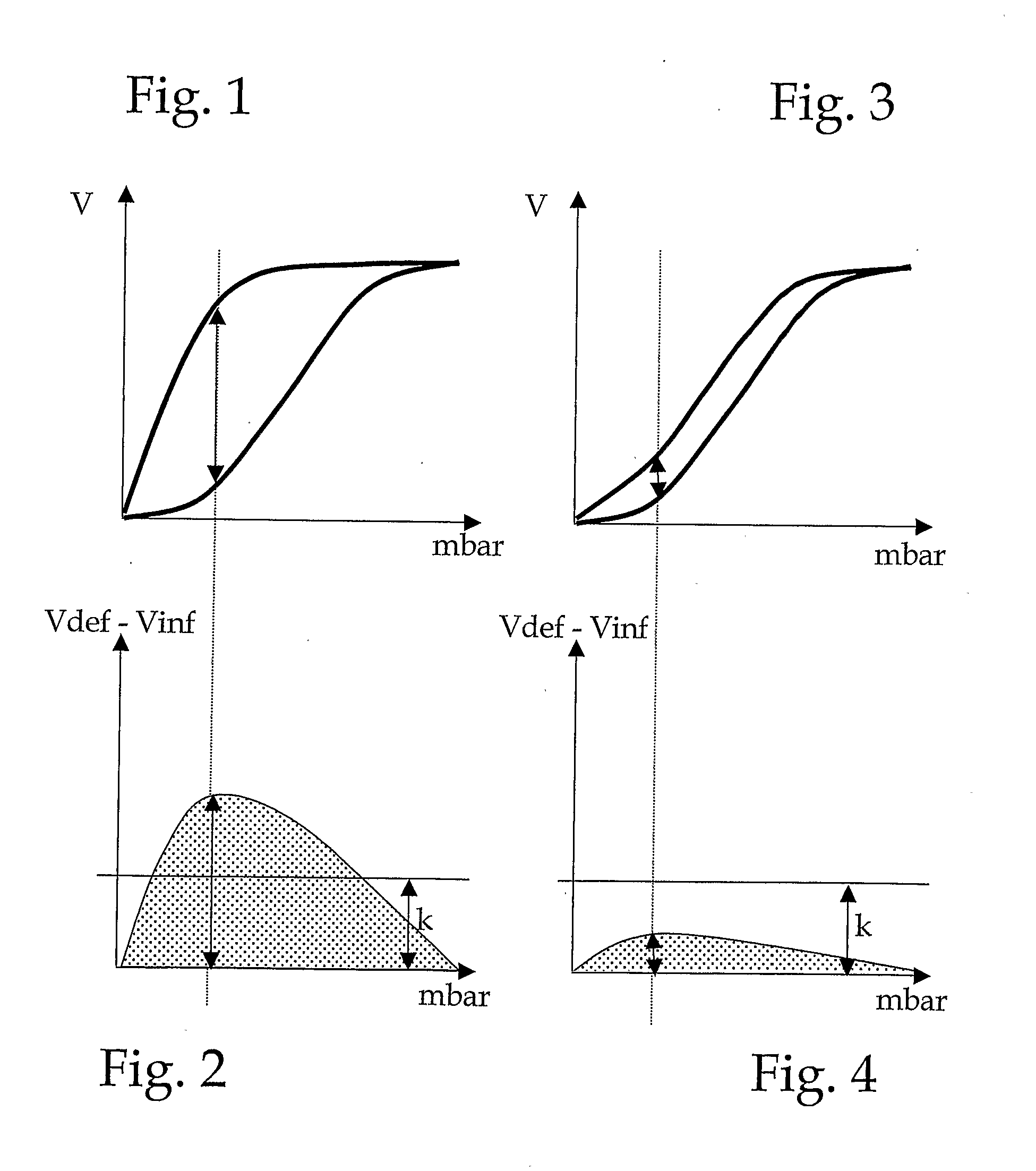
[0049]In the following, the invention will be described in detail using the diagrams shown in FIGS. 1 to 4. Figure one shows a P / V loop of a patient whose lungs are better ventilated using a PEEP. The lower ascending branch is formed in that the lungs are inflated, and the volume of the air blown in is plotted relative to the prevailing pressure. The upper descending branch is recorded while air escapes from the lungs and thus the pressure is reduced. In this connection, the air volume remaining in the lungs is plotted in relation to the prevailing pressure. The great difference between the ascending lower branch and the descending upper branch permits the conclusion that pulmonary alveoli have collapsed at a low ventilation pressure, but are open at a higher ventilation pressure.
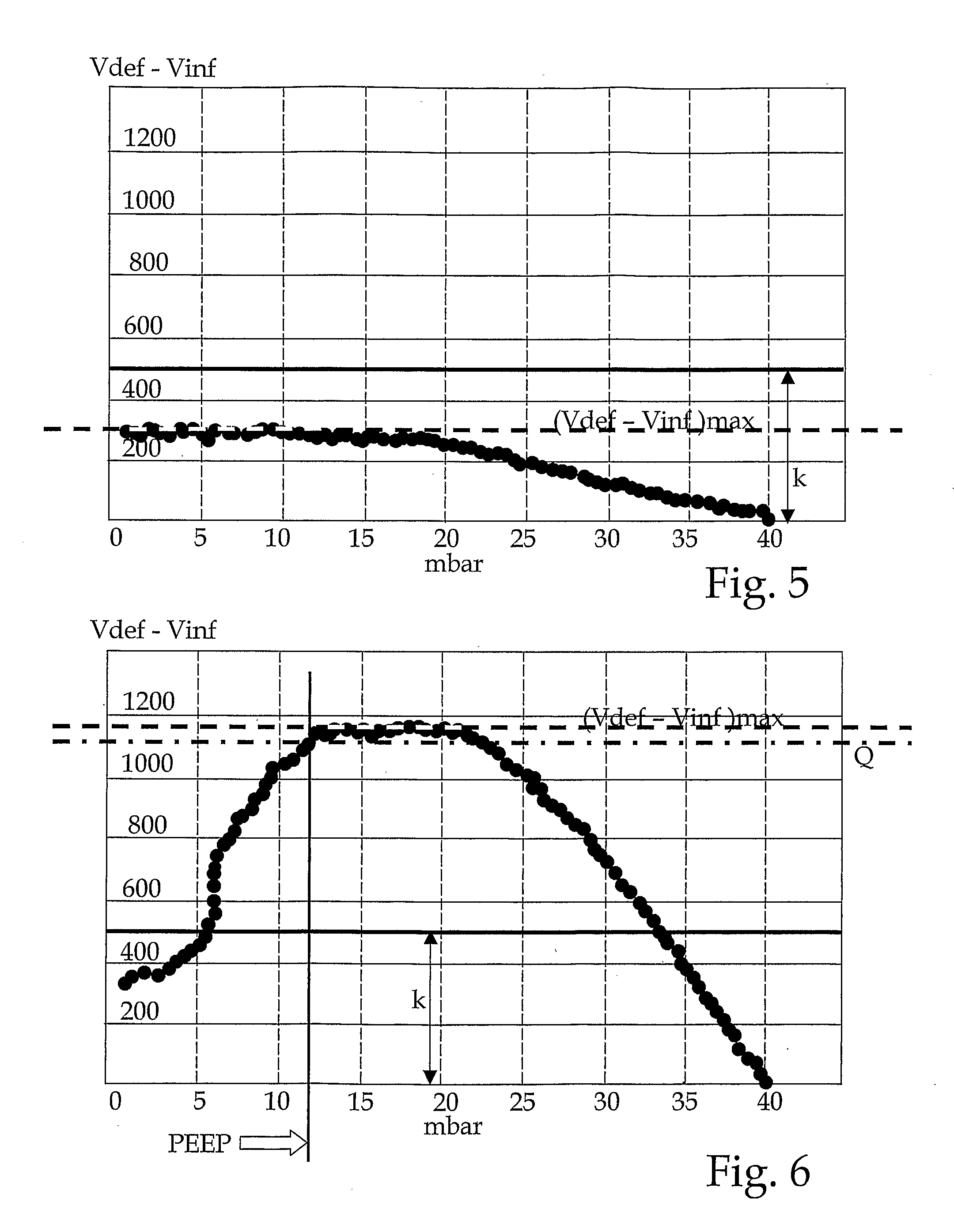
[0050]For the physician, the question arises at what—lowest possible—PEEP the pulmonary alveoli that have been recruited will remain open. It was found that the appropriate PEEP can be read off on the loop,...
PUM
 Abstract
Description
Claims
Application Information