
Implantable medical device with slotted housing serving as an antenna

a medical device and slotted housing technology, applied in the field can solve the problems of low transmission data rate, limited use of implantable medical devices, and operating distance of this technique, and achieve the effects of low cost, convenient manufacturing, and convenient tuning

Inactive Publication Date: 2006-12-12
ST JUDE MEDICAL
View PDF15 Cites 58 Cited by
  • Summary
  • Abstract
  • Description
  • Claims
  • Application Information

AI Technical Summary

Benefits of technology

[0014]It is a particular object of the invention to provide such an implantable medical device that exhibits an overall improved antenna performance in comparison to known implantable medical devices. Higher antenna efficiency implies increased usable range for an exterior antenna.
[0018]A still further object of the invention is to provide such an implantable medical device, in which the antenna is easy to manufacture to a low cost, easy to tune, and wherein the antenna enables an efficient use of available space.
[0019]Another object of the invention is to provide such an implantable medical device that is reliable and particularly mechanically durable.
[0022]If conducting leads, such as those used in a cardiac pacemaker device, i.e. electrode leads, are provided, they can be arranged to extend from the electrically conductive housing close to a voltage node of an electromagnetic field as arises when the electrically conductive housing operates as an antenna for the radio frequency telemetry signals. This results in a minimum interference between the conducting leads and the antenna function.

Problems solved by technology

Due to the very poor operating distance of this technique, the exterior antenna had to be located in close proximity to the implantable device, typically within a few inches.
Further, the communication suffered from low transmission data rate.
Although U.S. patent application Publication 2002 / 0095195 discloses a manner to utilize the limited space for the antenna function, but, nevertheless, there are several limitations as to the use of an implantable medical device in which two separated conductive halves of the housing act as a dipole antenna.
First, because the header, made of dielectric material, is disposed between the two conductive halves, this allows external interfering radiation to enter the implantable device and interfere with signals transmitted within any of the two conductive halves or with signals transmitted across the dielectric header.
Third, the design of the implantable medical device does not allow for an optimum location of the conducting leads with respect to possible interference of the therapy signals by radio frequency signals fed to or received by the dipole antenna.
Finally, the mechanical structure of this known implantable medical device seems not to be optimum, because two housing portions of a conductive material have to produced, and must be fixed to and hermetically sealed against an intermediate piece of dielectric material.
The manufacturing is further complicated by the need for a number of feed-throughs.

Method used


Image

  • Implantable medical device with slotted housing serving as an antenna
  • Implantable medical device with slotted housing serving as an antenna
  • Implantable medical device with slotted housing serving as an antenna

Examples


Embodiment Construction

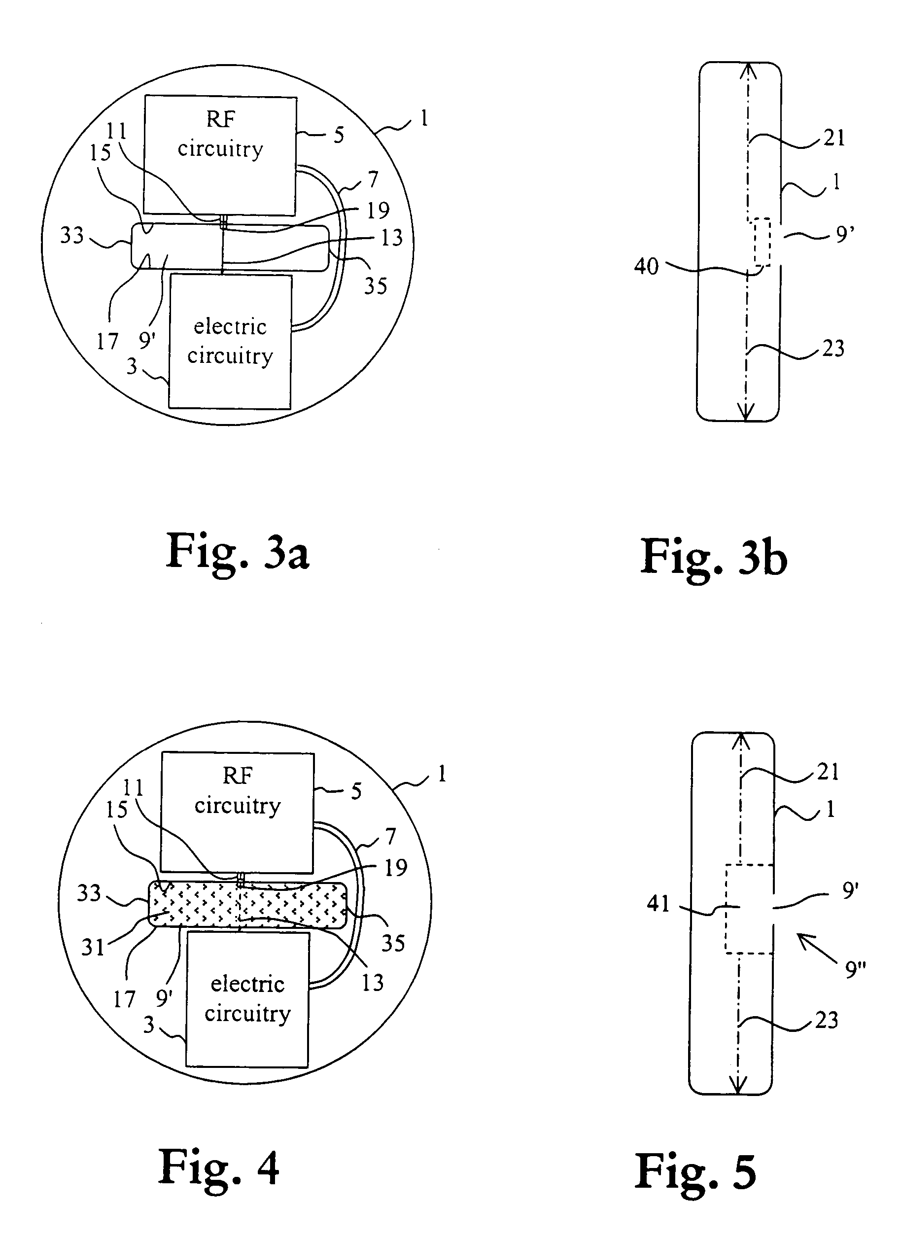
[0035]Throughout the figures similar parts and components, and portions thereof, are denoted by identical reference numerals.

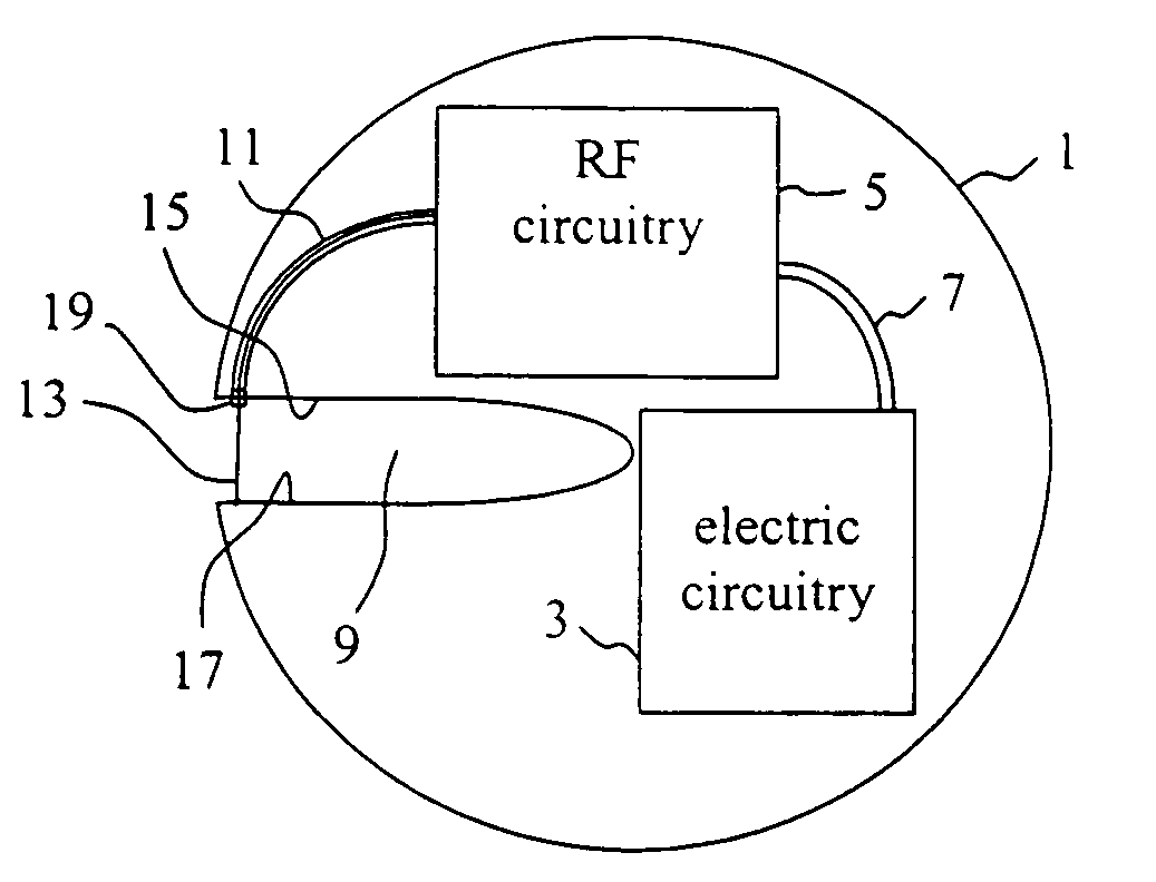
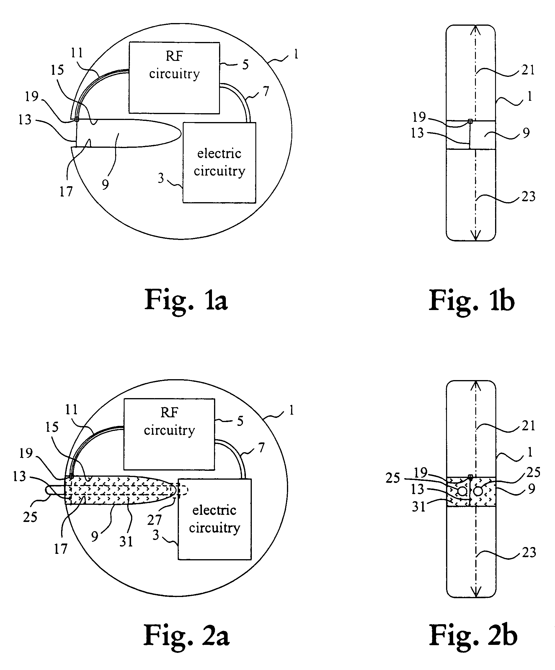
[0036]A first preferred embodiment of an implantable medical device of the present invention will be described with reference to FIGS. 1a and 1b. The implantable medical device may be e.g. a pacemaker, an insulin dispenser or other medical equipment including a telemetry link, preferably a high frequency telemetry link.

[0037]The implantable medical device has an electrically conductive hollow housing 1, electric circuitry 3 for the operation of the implantable medical device (i.e., for administering a medical therapy), and radio frequency circuitry 5 for transmitting and / or receiving radio telemetry frequency signals. The electric circuitry 3 and the radio frequency circuitry 5 are interconnected (schematically indicated at 7) and are arranged in the electrically conductive housing 1 in a common space or in separate compartments, which may be shielded from eac...


PUM


Abstract

An implantable medical device has a conductive housing, electronic circuitry for the operation of the implantable medical device, and radio frequency circuitry for transmitting and / or receiving radio frequency signals, the electronic circuitry and the radio frequency circuitry being interconnected and arranged within in the housing. The housing has at least one slot therein, and a slot feed operatively interconnected between the radio frequency circuitry and the slot. The electrically conductive housing provided with the at least one slot is operable as an antenna for the radio frequency signals. The electric circuitry, the radio frequency circuitry, and the interconnection can be enclosed by the housing so that they are shielded from external radiation in any direction.

Description

BACKGROUND OF THE INVENTION[0001]1. Field of the Invention[0002]The present invention relates to an implantable medical device.[0003]2. Description of the Prior Art[0004]In an implantable medical device, such as a cardiac pacemaker, an implantable cardioverter / defibrillator, or an insulin dispenser, telemetry is used e.g. to change or modify operation characteristics of the implantable device or to read out data from the implantable medical device to monitor its functioning or to obtain information about the patient in whom the device is implanted. Telemetry systems for implantable medical devices have utilized radio-frequency energy to enable communication between the implantable device and an external programmer device.[0005]Earlier telemetry systems used a rather low radio frequency, i.e. 13.5 MHz, as a carrier wavelength for communication between an antenna of the implantable device and an antenna of the external programmer device, which were inductively coupled to each other. D...

Claims


Application Information

Patent Timeline
Patent Type & Authority Patents(United States)
IPC IPC(8): A61N1/372A61N1/375
CPCA61N1/3752
Inventor EDVARDSSON, KURT OLOV
Owner ST JUDE MEDICAL
Learn More