
Hub drive and method of using same

a technology of hub drive and rotating wheel, which is applied in the direction of electric propulsion mounting, braking system, tractors, etc., can solve the problems of complex system, large complexity and size of the motive force system, and difficult installation and maintenance of complex systems

Inactive Publication Date: 2006-12-19
LOCKHEED MARTIN CORP
View PDF13 Cites 32 Cited by
  • Summary
  • Abstract
  • Description
  • Claims
  • Application Information

AI Technical Summary

Benefits of technology

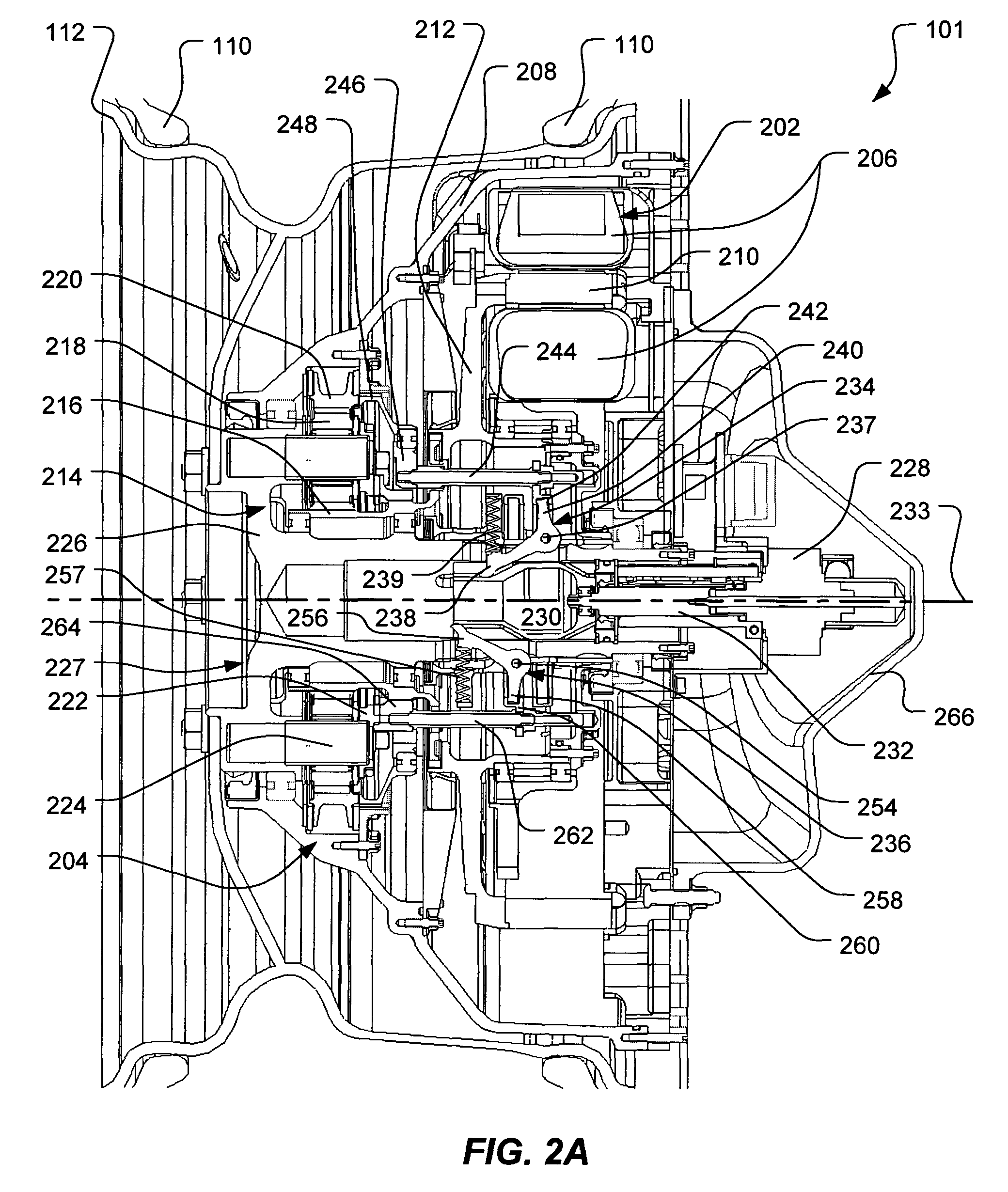
The present invention provides a hub drive with an in-hub motor and a shifting in-hub transmission for rotating a wheel. The hub drive wheel assembly includes a wheel with an in-hub motor and a shifting in-hub transmission for smooth acceleration and deceleration. The vehicle includes a chassis and a wheel with an in-hub motor and a shifting in-hub transmission for efficient driving. The method involves providing a shifting transmission and a motor in the hub of a wheel, supplying power to the motor, and rotating the wheel with the transmission. The technical effects of the invention include improved acceleration, deceleration, and efficiency of vehicle driving.

Problems solved by technology

Such systems used to provide a motive force to wheels of ground vehicles are often large, heavy and complex.
In applications wherein it is desirable for some or all of the wheels to be capable of being driven independently (i.e., at different speeds), the complexity and size of the motive force system may increase dramatically.
Such complex systems often are difficult to install and maintain and may be prone to failure merely due to their complexity.
Conventional systems may also limit the types of suspensions possible for the vehicle, due to difficulties encountered in routing power transmitting elements therethrough.
Further, conventional vehicles often experience a jolt or hesitation during transmission shifting, which may be undesirable depending upon the use of the vehicle.
For example, if the vehicle is being used to transport a gun or the like, such jolting or hesitation may decrease the accuracy of the gun, if it is fired while the vehicle is being operated.

Method used


Image

  • Hub drive and method of using same
  • Hub drive and method of using same
  • Hub drive and method of using same

Examples


Embodiment Construction

[0020]Illustrative embodiments of the invention are described below. In the interest of clarity, not all features of an actual implementation are described in this specification. It will of course be appreciated that in the development of any such actual embodiment, numerous implementation-specific decisions must be made to achieve the developer's specific goals, such as compliance with system-related and business-related constraints, which will vary from one implementation to another. Moreover, it will be appreciated that such a development effort might be complex and time-consuming but would nevertheless be a routine undertaking for those of ordinary skill in the art having the benefit of this disclosure.

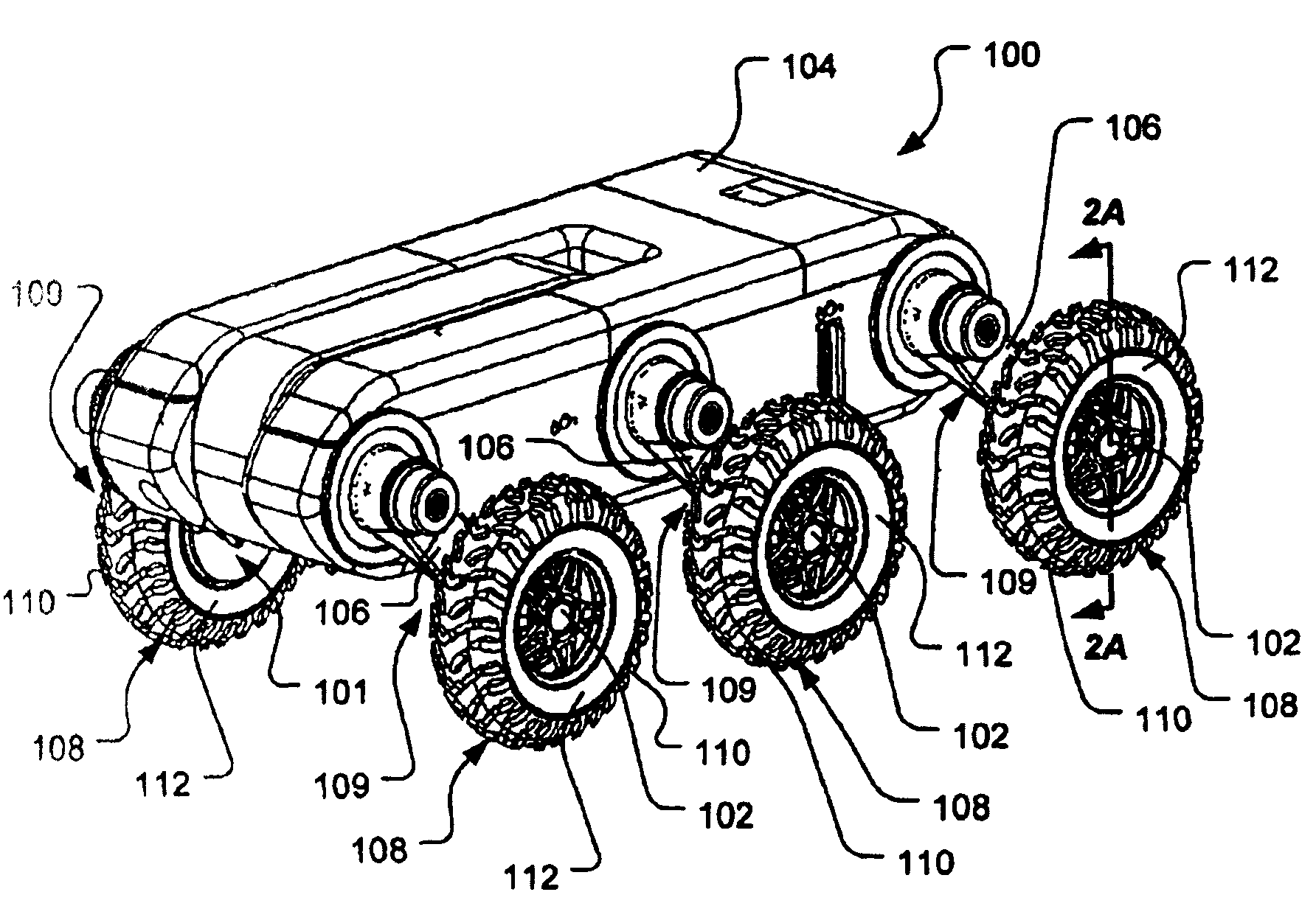
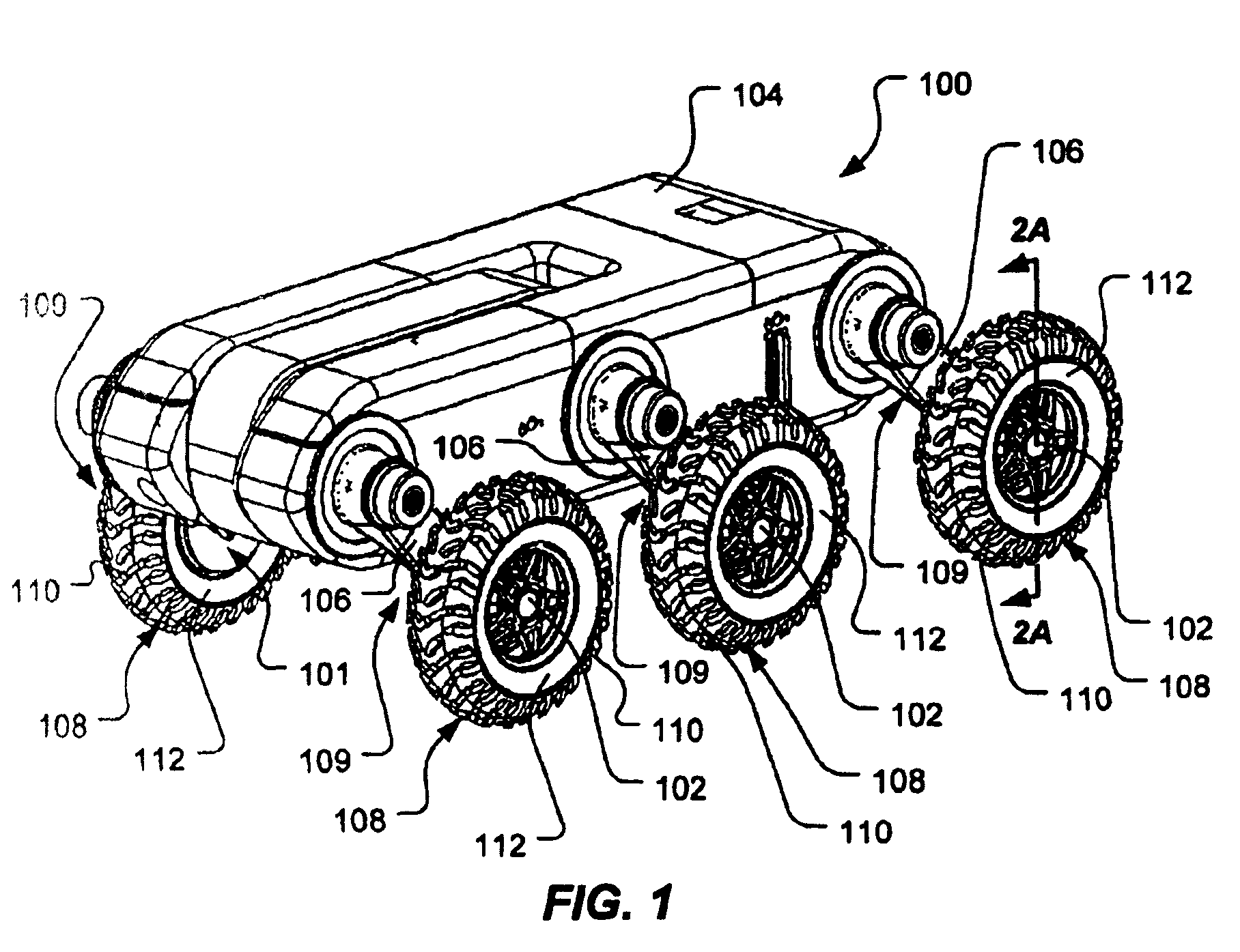
[0021]FIG. 1 is a pictorial view of a vehicle 100 according to the present invention. The vehicle 100 comprises a plurality of wheels 108 that, when rotated while in contact with a surface, allows the vehicle to traverse the surface. Each of the wheels 108 is rotated with respect ...


PUM


Abstract

A hub drive includes an in-hub motor and a shifting in-hub transmission coupled with the motor. A hub drive wheel assembly includes a wheel comprising a hub, an in-hub motor, and a shifting in-hub transmission having an input attached to the motor and an output attached to the wheel. A vehicle includes a chassis, a wheel comprising a hub, an in-hub motor, and a shifting in-hub transmission having an input attached to the motor and an output attached to the wheel for rotating the wheel with respect to the chassis. A method includes providing a shifting transmission and a motor coupled with the transmission in a hub of a wheel, providing electrical power to the motor, and rotating the motor with the electrical power. The method further includes rotating the transmission with the motor and rotating the wheel with the transmission.

Description

[0001]We claim the earlier effective filing date of co-pending U.S. Provisional Application Ser. No. 60 / 449,271, entitled “Unmanned Ground Vehicle,” filed Feb. 21, 2003, in the name of Michael S. Beck, et al., for all common subject matter.BACKGROUND OF THE INVENTION[0002]1. Field of the Invention[0003]This invention relates to a drive for rotating a wheel and, in particular, to a hub drive for rotating a wheel.[0004]2. Description of the Related Art[0005]Wheeled ground vehicles have been used for many years to carry personnel, cargo, and other equipment. Such vehicles generally have some means of producing a motive force to the wheels, such as an engine or motor in combination with a drive train. For example, in a rear-wheel drive automobile, an engine generates the motive force for propelling the automobile and the drive train includes a transmission, drive shaft, differential, and driven axles. The transmission, which is rotationally coupled with the engine, allows the automobile...

Claims


Application Information

Patent Timeline
Patent Type & Authority Patents(United States)
IPC IPC(8): B60K17/356B60K1/00B60K7/00B60K17/02B60K17/04B60K28/16B60T1/06B62D49/00B62D61/10B62D61/12B64B1/50B64C27/20B64C39/02B64G1/16
CPCB60K7/0007B60K17/02B60K17/046B60K17/356B60K28/16B60T1/062B62D49/002B62D61/10B62D61/12B64G1/16B60K7/00B60K2007/0038B60K2007/0092B60W2520/28B60W2530/10
Inventor BECK, MICHAEL S.STINCHCOMB, JON T.CHUN, WENDELL H.CLEMENS, DAVID A.DUNNE, JOHN C.BANKS, DEAN
Owner LOCKHEED MARTIN CORP
Learn More