Wheel rotational speed controlled vehicle illumination system

Inactive Publication Date: 2006-12-19
BURNETT MARQUIS +1
View PDF15 Cites 20 Cited by
  • Summary
  • Abstract
  • Description
  • Claims
  • Application Information

AI Technical Summary

Benefits of technology

[0010]The tires of the automobile often carry labels and identifying marks, but these marks promote the tire companies and their products, not the individual. The system of the present invention allows the individual to place the individual's mark, name, slogan, etc. on the exterior of a tire by application of pliable or non-pliable materials, paint, or surface preparation that can be seen by individuals in close proximity to the tire. Further, this system allows for better viewing of any mark, name, slogan or drawing on the tire and the design of the wheel, especially when the tire and automobile are in motion. Th

Problems solved by technology

However, this location is not desirable for the traveling vehicle due to high speed tire rotation.
Stroboscopes in the art are not designed for displaying information on t

Method used


Image

  • Wheel rotational speed controlled vehicle illumination system
  • Wheel rotational speed controlled vehicle illumination system
  • Wheel rotational speed controlled vehicle illumination system

Examples


Embodiment Construction

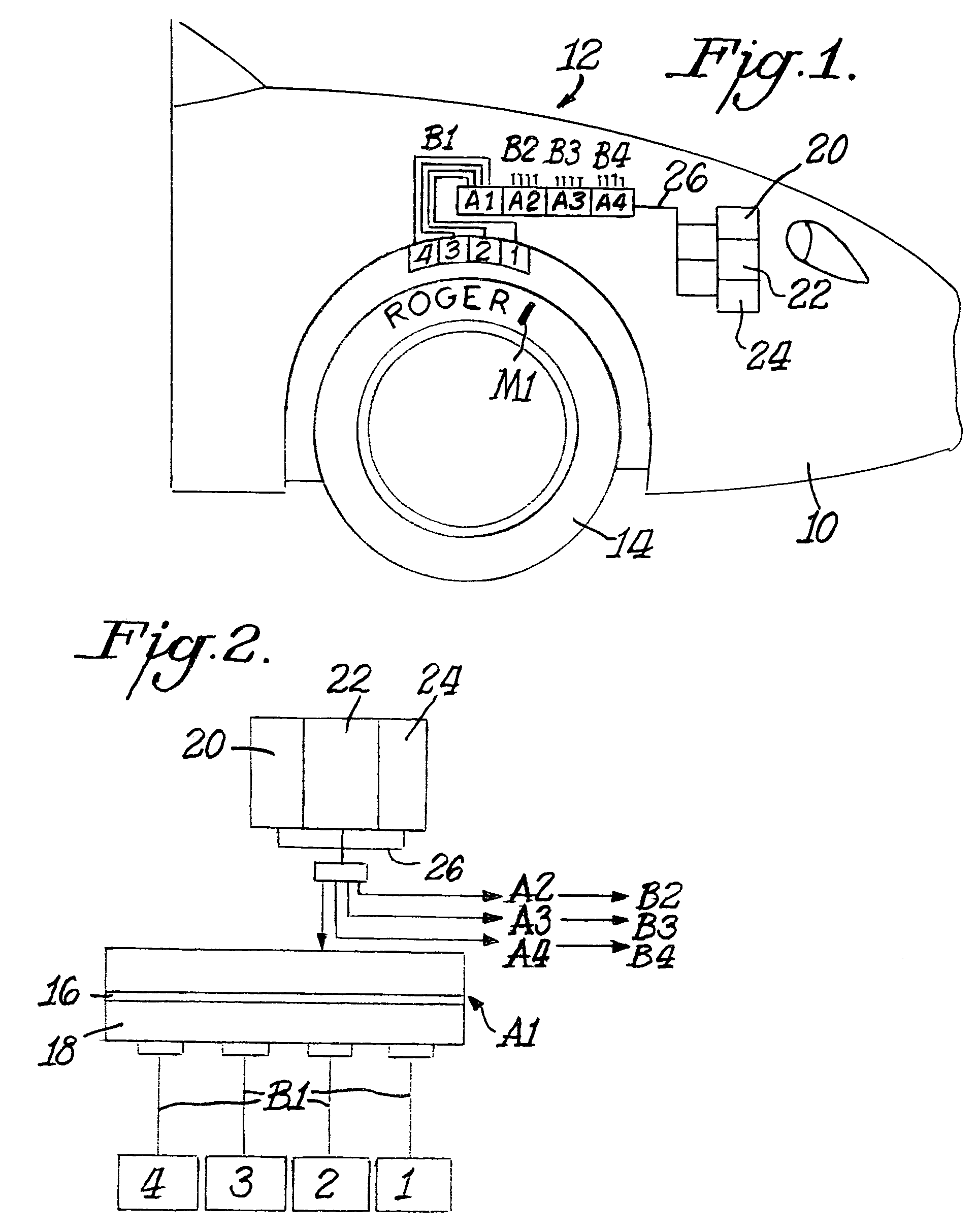
[0064]Referring in more particularity to the drawings, FIG. 1 shows the front end of an automobile 10 including a vehicle tire illumination system 12, according to the present invention. A microchip logic unit A1 is provided for the vehicle tire 14 illustrated in FIG. 1, it being understood that identical microchip logic units A2, A3 and A4 are also provided, one for each of the other vehicle tires (not shown). Each microchip logic unit includes a circuit board 16 and a hardware base 18. Basically the hardware base includes four components identified in the drawings as 1, 2, 3 and 4, and explained in more detail below. Lines B1, B2, B3 and B4 interconnect units A1, A2, A3 and A4 to the component 1, 2, 3 and 4 associated with each wheel.

[0065]Power is supplied to each of the microchip logic units A1, A2, A3 and A4 from a condenser coil 20, power source 22 and backup battery 24. Conducting lines 26 are provided between these components.

[0066]Indicia such as the name “Roger” may be app...


PUM


Abstract

An illumination system has a housing that rotates with a vehicle wheel, and the housing has a cavity with lighting and controls within the cavity. Light from the cavity is directed onto a vehicle wheel, and the light flashes in relationship to the rotation speed of the wheel which makes the wheel appear to be stationary or slowly rotate in a backward or forward direction.

Description

REFERENCE TO RELATED APPLICATIONS[0001]The present application claims the benefit of provisional applications Ser. Nos. 60 / 317,068, filed Sep. 4, 2001, and 60 / 356,075, filed Feb. 11, 2002, and these applications are incorporated herein by reference for any and all useful purposes. Also, this application is a continuation-in-part of application Ser. No. 10 / 234,877, filed Sep. 4, 2002, now U.S. Pat. No. 6,641,041, which claims the benefit of the above identified provisional applications.BACKGROUND OF THE INVENTION[0002]This present invention relates to a logic-controlled light with an emitter and sensor which identify and shine a burst of light or radiation onto a rapidly moving or rotating or vibrating or repeating element, and an illuminating system or wheel containing the logic-controlled light. The lighting system illuminates the tire and / or wheel areas of a vehicle. In particular, the illuminating system may be used to make the wheel area, spokes and / or lugs selectively appear to...

Claims


Application Information

Patent Timeline
IPC IPC(8): B60Q1/32B60QB60Q1/00B60Q1/26G06K7/10G06K7/14
CPCB60Q1/326Y10S362/802
Inventor OLDS, ROGERBURNETT, MARQUISNG, JASON
Owner BURNETT MARQUIS
Why Eureka
Try Eureka