Surface mount electrical connector

Inactive Publication Date: 2006-12-19
TE CONNECTIVITY CORP
View PDF14 Cites 30 Cited by
  • Summary
  • Abstract
  • Description
  • Claims
  • Application Information

AI Technical Summary

Benefits of technology

[0006]Optionally, the dielectric member may include an alignment rib extending on an exterior surface thereof, wherein the contact abuts the alignment rib, and the alignment rib is oriented with respect to the solder tab to ensure coplanarity of the contact engagement surface with the solder tab engagement surface. The alignment rib may provide a positive force on the contact in a direction of the circuit board when the cont

Problems solved by technology

However, typical connector assemblies suffer from certain drawbacks.
For example, the plug connector may be easily disengaged from the jack connector and thus lose electrical contact therebetween.
This approach may be undesirable in an automobile production environment.
Other drawbacks to known connector assemblies include possible damage to the

Method used


Image

  • Surface mount electrical connector
  • Surface mount electrical connector
  • Surface mount electrical connector

Examples


Embodiment Construction

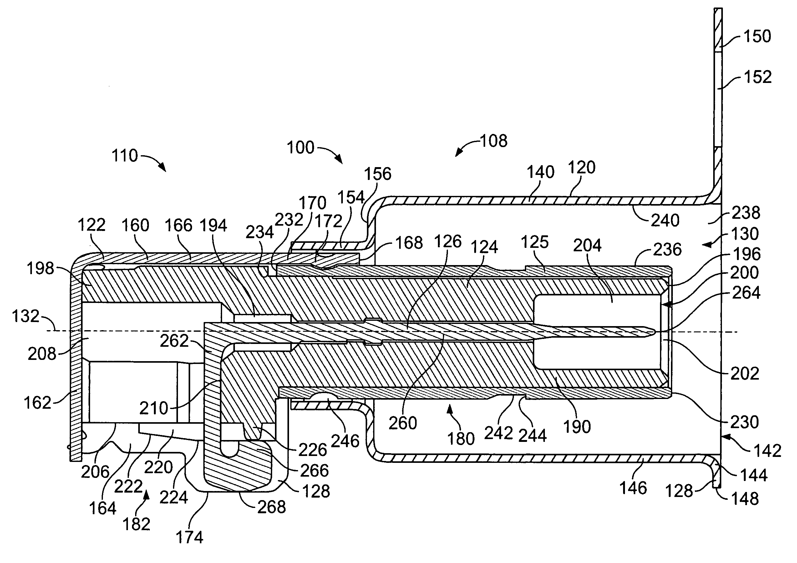
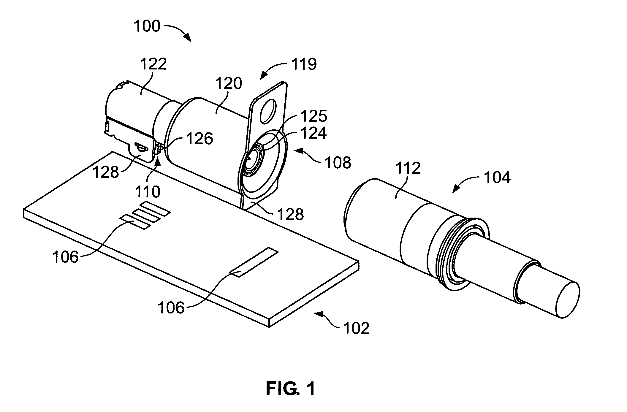
[0015]FIG. 1 is a top perspective view of an electrical connector 100 in accordance with an exemplary embodiment of the present invention, a circuit board 102, and a mating plug connector 104. The electrical connector 100 defines a jack connector that is surface mounted to the circuit board 102. Optionally, the electrical connector 100 is coupled to the circuit board 102 by a soldering process. For example, the electrical connector 100 may be soldered to the circuit board 102 at a plurality of predefined solder pads 106. As such, the electrical connector 100 is mechanically and electrically coupled to the circuit board 102. The electrical connector 100 is a right angle connector including a mating portion 108 configured to be mated with the mating plug connector 104 and a mounting portion 110 configured to be mounted to the circuit board 102. The mating portion 108 is oriented generally perpendicular with respect to the mounting portion 110.

[0016]The mating plug connector 104 is rec...


PUM


Abstract

An electrical connector includes an outer shell defining an inner cavity, wherein the outer shell includes a shell alignment element and a solder tab having a substantially flat solder tab engagement surface for surface mounting to a circuit board. An inner member is received within the inner cavity, and the inner member includes a dielectric member having a dielectric alignment element engaging the shell alignment element for positioning the dielectric member with respect to the outer shell. The dielectric member includes a contact cavity extending axially through the dielectric member. A contact is received within the contact cavity, and the contact includes a contact engagement surface for surface mounting to the circuit board. The contact and solder tab engagement surfaces are aligned in a predetermined planar arrangement.

Description

BACKGROUND OF THE INVENTION[0001]This invention relates generally to electrical connectors, and, more specifically, to surface mount snap lock electrical connectors for mating engagement with plug connectors.[0002]Many cars include radio antennas that are located on the roof of the car. The antenna or plug connector typically is connected to, and delivers an electric signal to, a jack connector located within the car. The jack connector is typically through hole mounted to a circuit board of a radio. The plug connector and the jack connector are secured to each other in mating contact to form a connector assembly.[0003]However, typical connector assemblies suffer from certain drawbacks. For example, the plug connector may be easily disengaged from the jack connector and thus lose electrical contact therebetween. As such, at least some connector assemblies include a connector locking assembly. The connector locking assembly is configured to be manually operated to release the plug co...

Claims


Application Information

Patent Timeline
IPC IPC(8): H01R9/05
CPCH01R24/50H01R12/57H01R13/6277H01R2103/00H01R2201/02
Inventor HALL, JOHN WESLEYRAUDENBUSH, JAMES MICHAELMOLL, HURLEY CHESTER
Owner TE CONNECTIVITY CORP
Why Eureka
Try Eureka