Tool changing device which prevents chips adhering to tool

a tool and chip technology, applied in the direction of electrical programme control, program control, instruments, etc., can solve the problems of device not being able to remove the chip adhering to the tapered portion of the tool, affecting the accuracy of forming, and difficulty in removing the tool

Inactive Publication Date: 2006-12-19
FANUC LTD
View PDF12 Cites 6 Cited by
  • Summary
  • Abstract
  • Description
  • Claims
  • Application Information

AI Technical Summary

Benefits of technology

[0011]It is an object of the present invention to resolve above-mentioned problem in prior art, and to prevent cuttings or chips from adhering to a tool of a machine tool without using any additional device.
[0012]In accordance with the present invention, by using a drive motor with which a tool changing device of the machine tool is usually provided, in order to vibrate the tool, the chips are prevented from adhering to the tool, e.g., a tapered portion of the tool, and / or the chips adhered to the tool are removed, without using any additional device.
[0015]In accordance with the first embodiment of the method of the present invention, there is provided a method for preventing chips adhering to a tool held in a tool magazine of a tool changing device of a machine tool, the tool changing device comprising a tool magazine drive motor for indexing the tool magazine, the method comprising; holding the tool in the tool magazine; and vibratory driving of the tool magazine drive motor to vibrate the tool magazine in order to vibrate the tool.
[0017]In accordance with the second embodiment of the method of the present invention, there is provided a method for preventing chips adhering to a tool held by a tool changing arm of a tool changing device of a machine tool, the tool changing device comprising a tool changing arm drive motor for rotating the tool changing arm, the method comprising; holding the tool by the tool changing arm; and vibratory driving of the tool changing arm drive motor to vibrate the tool changing arm in order to vibrate the tool.

Problems solved by technology

If the chips adhere to a tapered portion of the tool, it may be difficult to exchange the tool with another tool, and the forming accuracy may deteriorate after the tool is changed.
The proposed devices for removing the chips have a problem that a coolant supplying unit or a mechanism such as a vibrator for removing the chips must be installed, additionally, on the machine tool.
Therefore, the device cannot remove the chips adhered to the tapered portion of the tool.

Method used


Image

  • Tool changing device which prevents chips adhering to tool
  • Tool changing device which prevents chips adhering to tool
  • Tool changing device which prevents chips adhering to tool

Examples


Embodiment Construction

[0030]In the following, embodiments of the invention will be described with reference to the drawings.

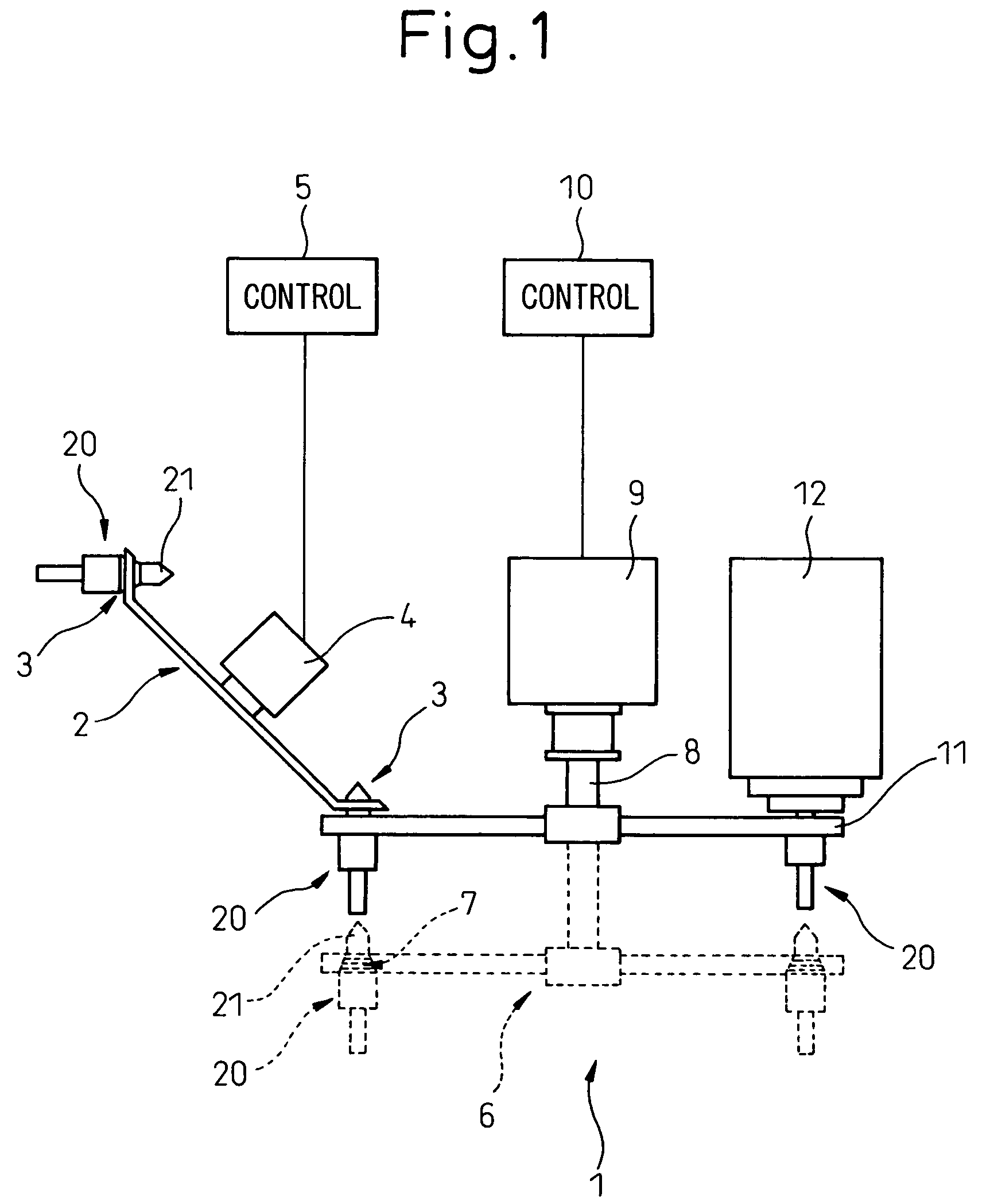
[0031]FIG. 1 shows a scheme for explaining a tool changing device of the invention. In addition, the construction of a machine tool is omitted in FIG. 1.

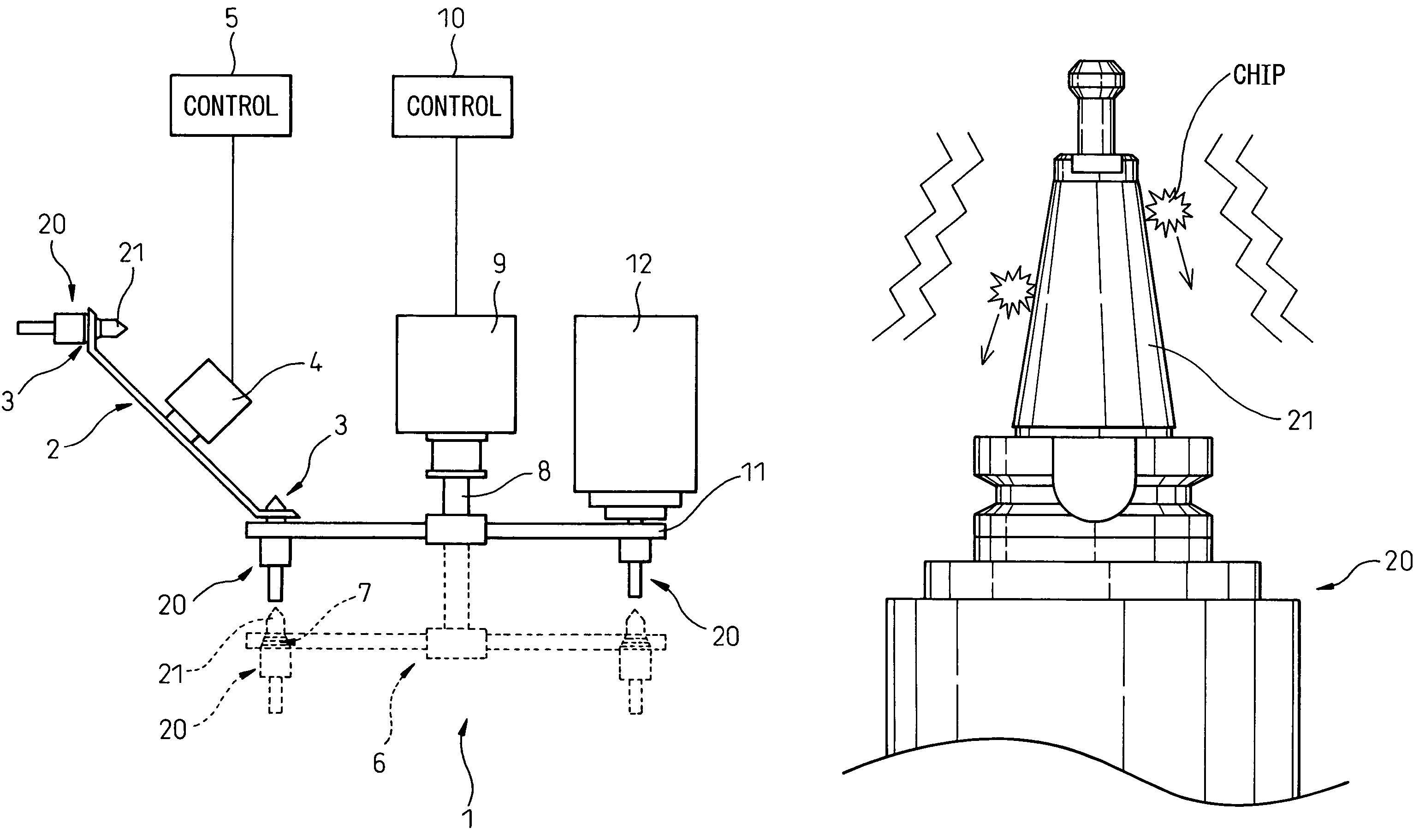
[0032]Referring to the FIG. 1, a machine tool performs machining, such as cutting, by mounting a selected tool 20 on a machining spindle 11 and driving the spindle 11 by a machining drive 12. The mounting of the tool 20 on the spindle 11 is performed through a tapered portion 21 arranged on the tool 20. This tool driving system for the tool 20 depicted in FIG. 1 is merely an example and, therefore, the system may use other configuration.

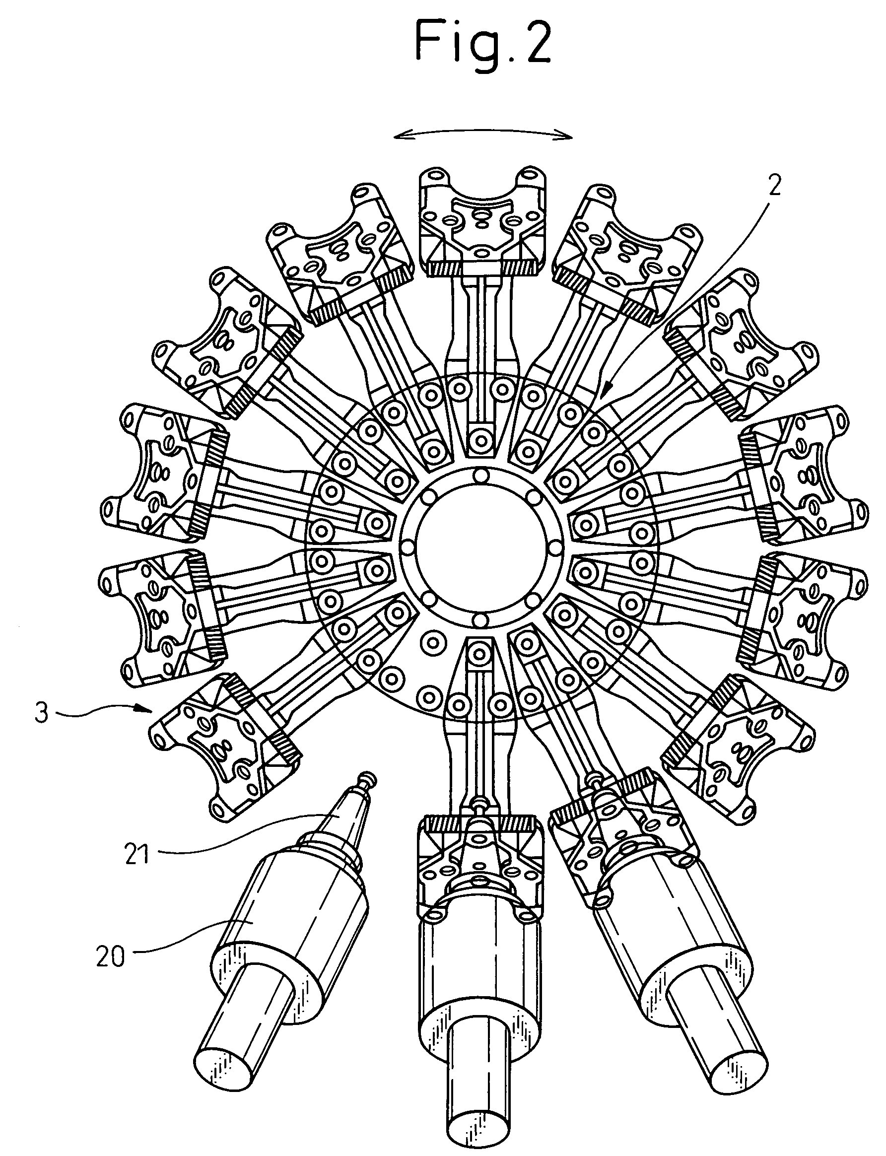
[0033]A tool changing device 1 includes a tool magazine 2 holding a plurality of tools 20, and a tool changing arm 6. The tool changing device 1 takes out a tool suitable for a object to be machined or a machining manner, from among the plurality of tools 20 held in the tool magazine 2, and replace a...


PUM


Abstract

A tool changing device of a machine tool which prevents chips adhering to a tool. By using a drive motor with which a tool changing device of the machine tool is usually provided, to vibrate the tool, the chips are prevented from adhering to the tool, especially to a tapered portion of the tool, and / or the chips adhered to the tool are removed, without using any additional device.

Description

BACKGROUND OF THE INVENTION[0001]1. Field of the Invention[0002]The present invention relates to a tool changing device of a machine tool.[0003]2. Description of the Related Art[0004]In a machine tool, in order to improve forming accuracy and extend the lifetime of a tool, a coolant liquid is supplied to a cutting point of a workpiece being cut by the tool. Moreover, in order to prevent cuttings or chips of the workpiece from scattering, the cutting point may be covered by coolant sprayed as a curtain.[0005]In such a machine tool, the chips may be scattered with the coolant and may adhere, with the coolant, to some parts of the machine tool during processing. If the chips adhere to a tapered portion of the tool, it may be difficult to exchange the tool with another tool, and the forming accuracy may deteriorate after the tool is changed.[0006]Therefore, Japanese Patent Publication (Kokai) No. 2002-273640 discloses a cleaning device, for a machine tool, which can remove chips adhered...

Claims


Application Information

Patent Timeline
Patent Type & Authority Patents(United States)
IPC IPC(8): B23Q3/157B23Q11/00B23Q3/155
CPCB23Q3/15526B23Q3/1554B23Q11/0053Y10T483/12Y10T483/176Y10T483/19Y10T483/10Y10T483/1755Y10T483/11Y10T483/1873Y10T483/15Y10T483/1882B23Q3/15534B23Q2003/155439Y02P70/10B23Q3/15722B23Q2003/155428B23Q2003/155418
Inventor KOJIMA, KUNIOSATO, NAOKI
Owner FANUC LTD
Why Eureka
Try Eureka