Method of transmitting a data packet

a data packet and transmission method technology, applied in the field of transmitting a data packet, can solve the problems of large time interval between the individual transmit authorization and the resultant delay jitter, large amount of bandwidth available, so as to prevent collisions and reduce the effect of data ra

Inactive Publication Date: 2006-12-19
WSOU INVESTMENTS LLC
View PDF17 Cites 5 Cited by
  • Summary
  • Abstract
  • Description
  • Claims
  • Application Information

AI Technical Summary

Benefits of technology

[0017]The first transmitting/receiving device has the form for example of a terminal, cable modem or radio station of a multiple access system. The second transmitting/receiving device has the form for example of a control centre, head end or hub of a HFC- or HFR system, a control centre of a hyperLAN-system or a base station of a LMDS- or UMTS-system. The multiple access system is for example a point-to-multipoint system with a control centre and a plurality of terminals. The second transmitting/receiving device forms the control centre, while the first transmitting/receiving device forms a terminal. The access method for the terminals to the transmission channel to the control centre is centrally controlled. In the case of TDMA, the control centre confers transmit authorizations by allocating time slots in which a specified terminal is authorized to transmit. The central allocation serves to prevent collisions. The transmit authorizations and the data packets sent by the terminals are not synchronised with one another. The data packets of the terminal

Problems solved by technology

If transmit authorizations are sent to a terminal at a low rate, for example a rate which corresponds to the traffic volume of a VolP application, the time intervals between the individual transmit authorizations and the resultant delay jitter are very large.
However, the increased transmit authorization rate inevitably leads to a bandwidth provision which greatly exc

Method used


Image

  • Method of transmitting a data packet
  • Method of transmitting a data packet

Examples


Embodiment Construction

[0026]In the following the invention will be explained in the form of an exemplary embodiment.

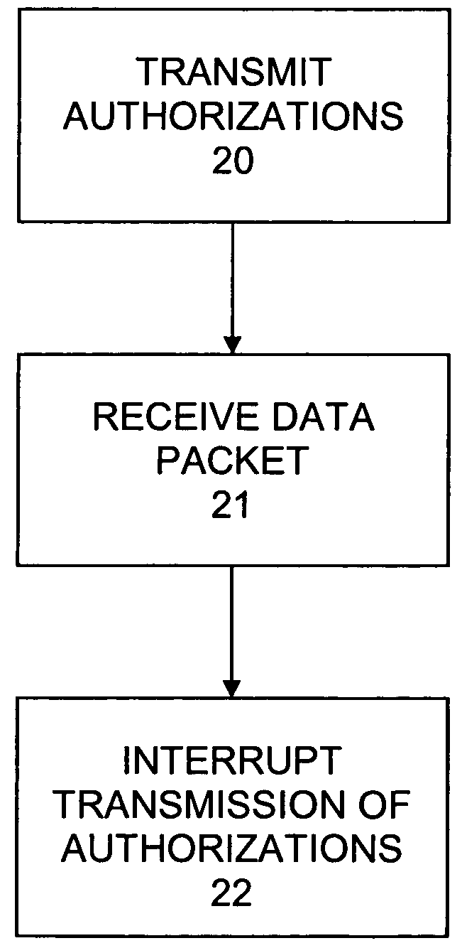
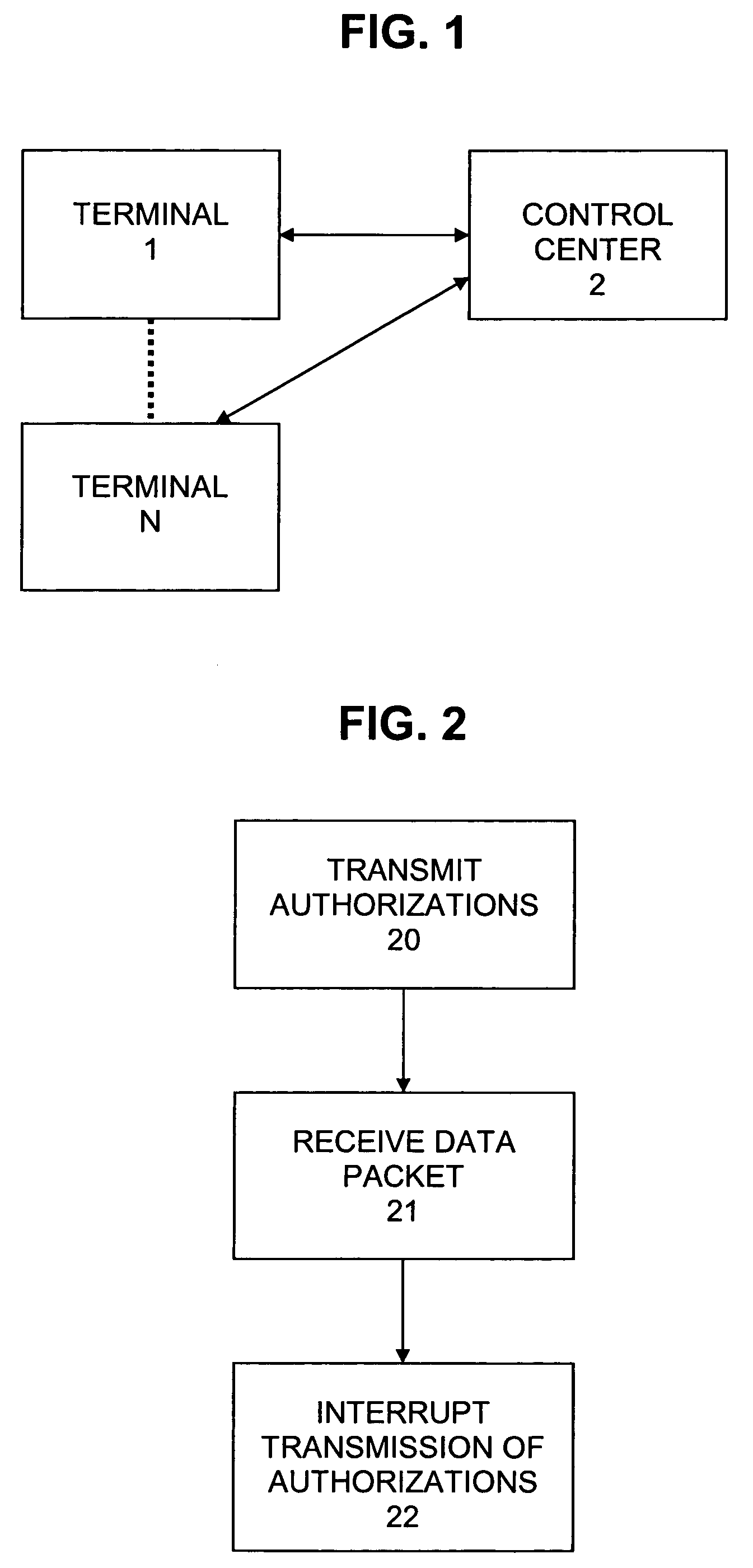
[0027]In the case of a VolP application, a terminal generates for example a data rate of 10 kbit / s. In this way data packets containing voice information are transmitted at a data rate of 10 kbit / s. For this purpose the control centre of the multiple access system must make available a transmit authorization rate of approximately one transmit authorization every 40 ms. The delay jitter is not to exceed 4 ms for example. In the multiple access system this would result in a data rate of 106 kbit / s for the VolP application. Due to the fact that the VolP application requires only 10 kbit / s, 96 kbit / s of the 106 kbit / s remain unused. In accordance with the invention, however, the transmission of the transmit authorizations is interrupted after the reception of a data packet for the corresponding terminal. If the VolP data packets arrive in the control centre for example with an inaccuracy of ±4 ...


PUM


Abstract

In a multiple access system, transmit authorizations are transmitted at a high rate in order to fulfil the requirements relating to the delay jitter. However, the transmit authorizations are transmitted only as long as is necessary. Following the reception of a data packet of a terminal, the transmission of further transmit authorizations for the same terminal is interrupted. Only after a specific time period, i.e. shortly before the expected transmission of a data packet of the same terminal, are transmit authorizations again sent to this terminal at a high data rate. In this way short time periods, in which transmit authorizations are sent to a terminal at a high rate, alternate with long time periods in which no transmit authorizations are sent to this terminal. In the long time periods, for example, transmit authorizations can be sent consecutively, in each case in short time periods, to one, two or more further terminals. In this way the bandwidth utilization is optimised.

Description

TECHNICAL FIELD [0001]The invention relates to a method of transmitting a data packet from a first transmitting / receiving device to a second transmitting / receiving device. The invention is based on a priority application DE 100 43 658.7 which is hereby incorporated by reference.BACKGROUND OF THE INVENTION [0002]Data packets are transmitted for example in multiple access systems. A multiple access system has the form for example of a point-to-multipoint system, for example a HFC-system, HFR-system, LMDS-system, UMTS-system or hyperLAN-system; HFC=Hybrid Fibre Coax, HFR=Hybrid Fibre Radio, LMDS=Local Multipoint Distribution System, UMTS=Universal Mobile Telecommunications System.[0003]In multiple access systems, in particular delay-sensitive, low-bandwidth services generate only small bandwidths on the path from the terminals to the control centre. Such services are for example VoIP, request signals for web pages, request signals for SoD or the like; VoIP=Voice over Internet Protocol=...

Claims


Application Information

Patent Timeline
IPC IPC(8): H04J3/14H04J3/06H04L12/26H04L12/56H04L12/64
CPCH04L12/6418H04W72/042H04L2012/6472H04L2012/6481H04L2012/6489H04W72/23
Inventor WAHL, STEFANSEIBOLD, WOLFRAM
Owner WSOU INVESTMENTS LLC
Why Eureka
Try Eureka