In situ molded thermal barriers

a thermal barrier and in situ technology, applied in fire prevention, building repairs, mechanical equipment, etc., can solve the problems of time-consuming and expensive installation of firestopping, gypsum wallboard expansion and contraction, and inability to mold, etc., to achieve excellent fire resistance and sealing ability, smoke and acoustic barrier properties, and high amenability to visual inspection

Inactive Publication Date: 2006-12-26
GCP APPL TECH INC
View PDF79 Cites 97 Cited by
  • Summary
  • Abstract
  • Description
  • Claims
  • Application Information

AI Technical Summary

Benefits of technology

The Firestop barriers created through this method have exceptional abilities to prevent fire outbreaks and block smokes and sounds during an emergency situation. These barriers can be easily installed and visually inspectable for strength against pressure.

Problems solved by technology

The technical problem addressed in this patent text is the need for a more convenient and cost-effective method for installing a thermal barrier in intricately shaped openings and joint gaps such as in "head-of-wall" joints, "perimeter" joints, and other variously sized and/or intricately shaped gaps or openings. The current methods of installing mineral wool and elastomeric coating are time-consuming, expensive, and require frequent repositioning of ladders. Novel thermal barriers and methods are needed to address these issues.

Method used


Image

  • In situ molded thermal barriers
  • In situ molded thermal barriers
  • In situ molded thermal barriers

Examples


Embodiment Construction

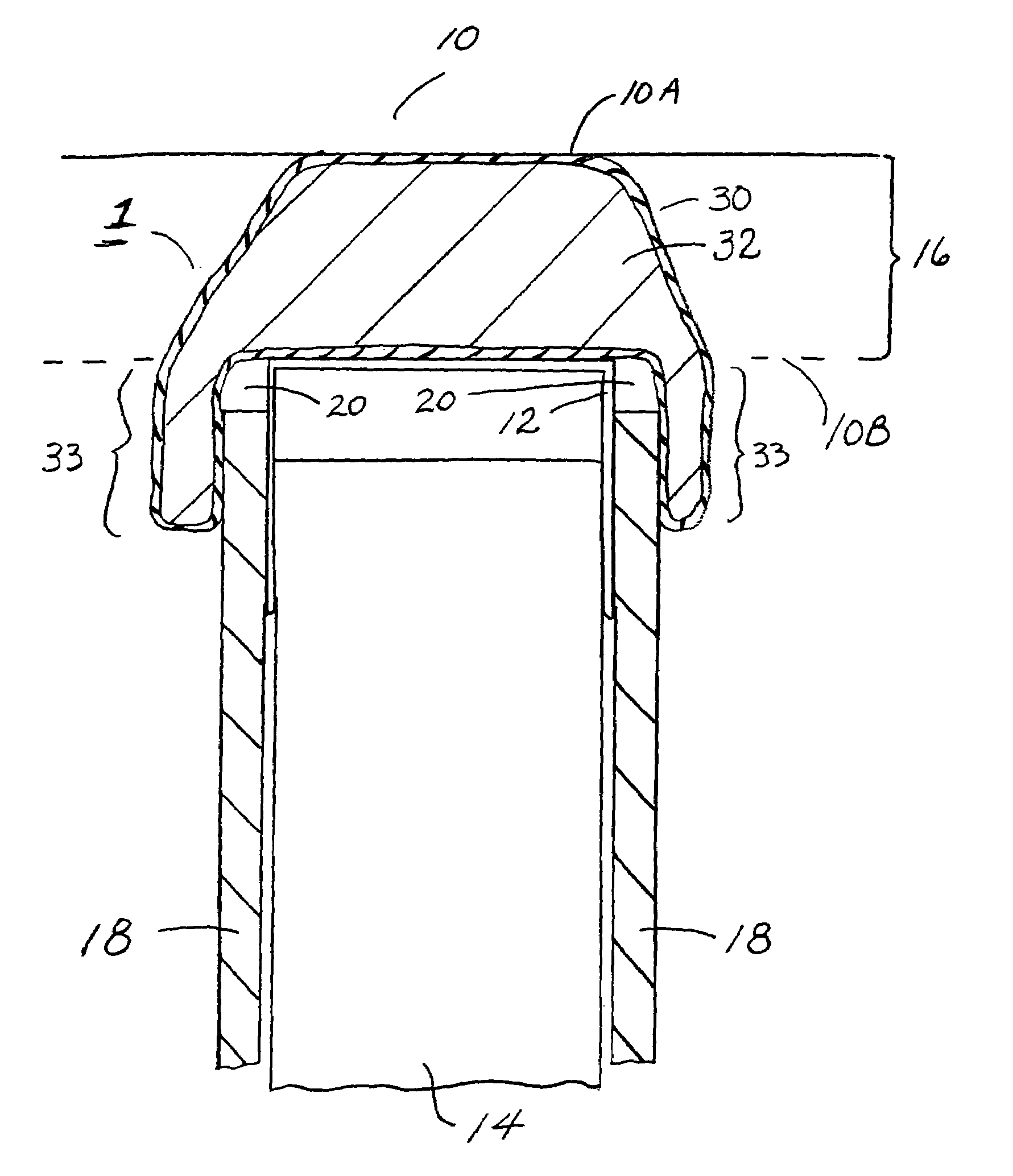
[0035]The present invention employs one or more thermal barrier molding bags that may be conveniently placed in openings in structure, such as a wall, ceiling, or floor, or conveniently placed in gaps such as are defined in the joints between walls, ceilings, and / or floors. The molding bags are placed empty in the hole or gap, and a flowable firestop material is introduced into the molding bag, thereby expanding the bag to fill the space within the hole or gap, and the flowable firestop material is then allowed to harden within the hold or gap to provide a strong thermal barrier. The term “firestop” as used herein is intended generally to refer to materials that are intended to be fire retardant or fireproofing in nature, and a detailed list of exemplary firestop or fireproofing materials is provided in the following paragraphs.

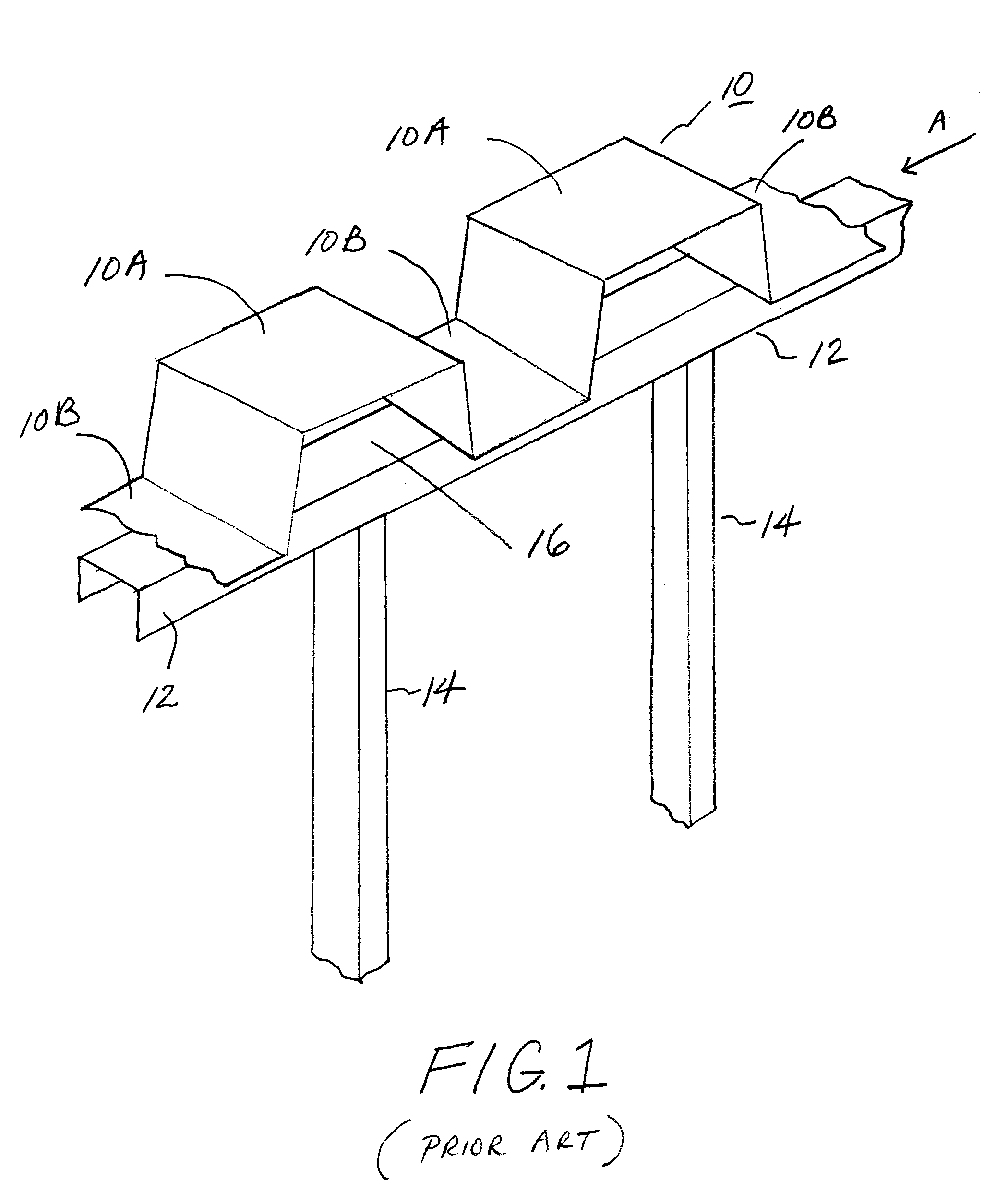
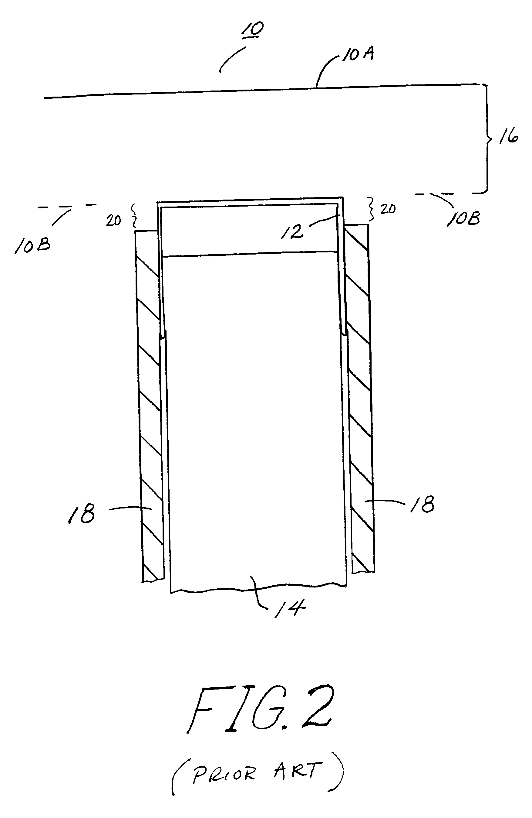
[0036]As shown in FIG. 1, a “head-of-wall” joint gap appears between the top of a vertical wall and ceiling (PRIOR ART). In this drawing, the wall is made by...


PUM

PropertyMeasurementUnit
Lengthaaaaaaaaaa

Abstract

Methods, systems, and devices for installing barriers in openings of gaps in or between structures such as walls, ceilings, and floors are described herein. At least one barrier molding bag is positioned in the hole or gap, and a flowable firestop material that is preferably operative to cure or harden, such as a hydratable cementitious slurry, is introduced into the bag to create a barrier in the hole or gap.

Description


Claims


Application Information

Patent Timeline
Owner GCP APPL TECH INC
Why Eureka
Try Eureka