Thermal energy recovery device

Inactive Publication Date: 2006-12-26
VOLVO TECH
View PDF22 Cites 8 Cited by
  • Summary
  • Abstract
  • Description
  • Claims
  • Application Information

AI Technical Summary

Benefits of technology

[0008]These objectives are achieved by way of the device comprising (including, but not being limited to) a body with a zigzag-shaped structure that forms ducts for said gas flows. The body is designed for

Problems solved by technology

Such a thermal energy recovery device has a potentially high efficiency, but it has proved difficult to manufacture such a device in a way that is sufficiently cost-effective for commercial production.

Method used


Image

  • Thermal energy recovery device
  • Thermal energy recovery device
  • Thermal energy recovery device

Examples


Embodiment Construction

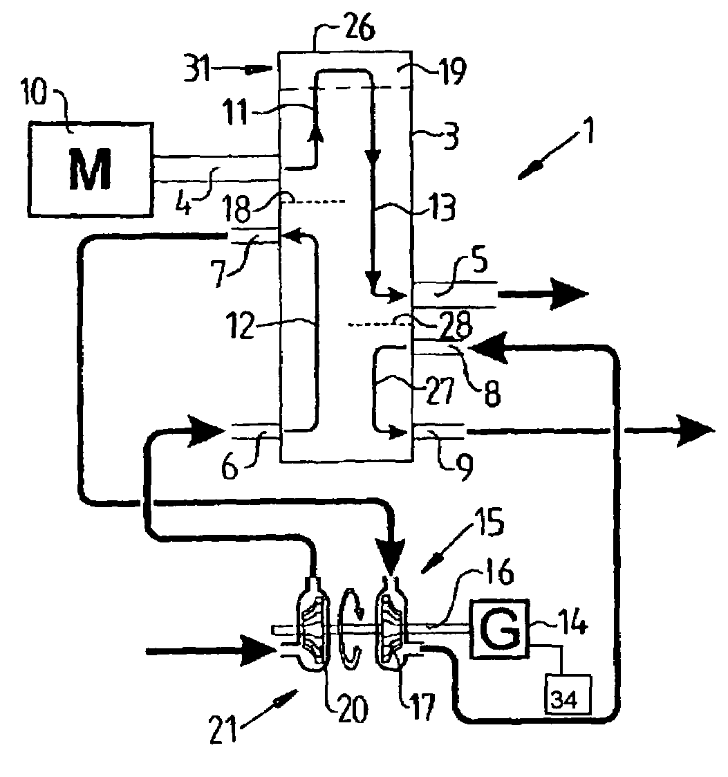
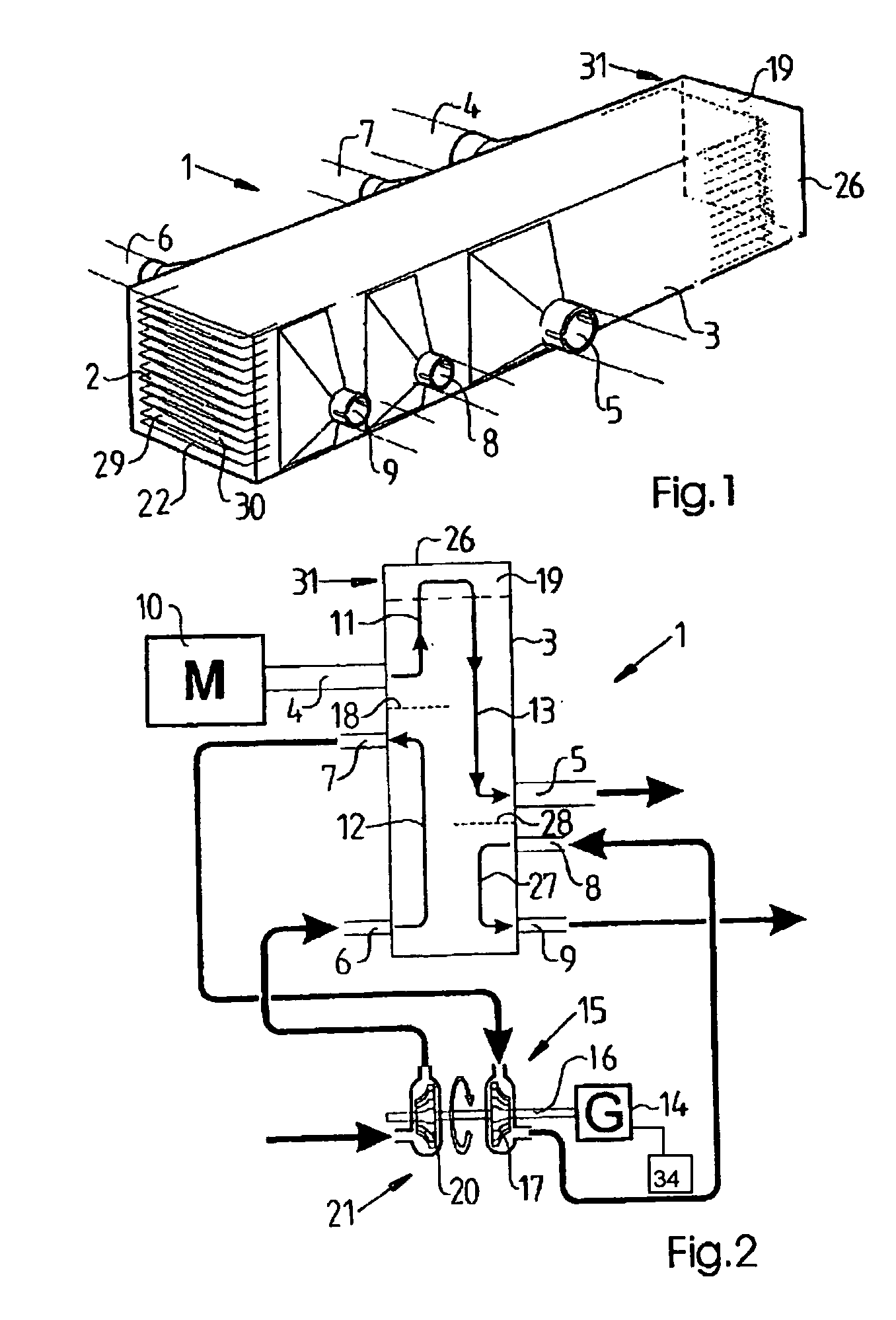
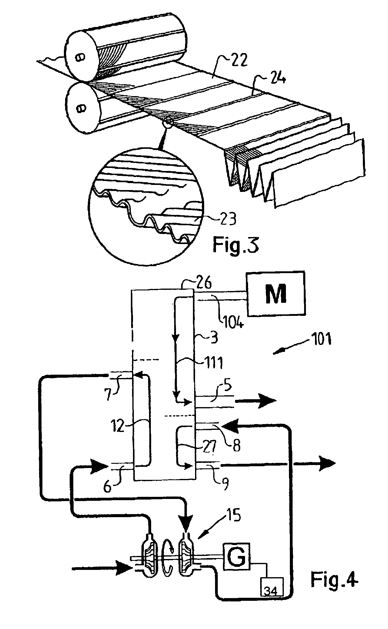
[0018]FIGS. 1 and 2 illustrate a device or apparatus 1 for the recovery of thermal energy from exhaust gases from an internal combustion engine 10. The device 1 comprises (includes, but is not limited to) a body 2, that defines a plurality of ducts 29, 30 for leading the gas flows in such a way that there is an exchange of heat between them. A casing 3 encloses the body 2. The casing 3 has a plurality of openings 4–9 for the admission of gases to, and the removal of gases from, the body 2.

[0019]The heat recovery is intended to occur through heat transfer from a first gas, that is the exhaust gases, which define a first gas flow 11, to a second gas flow 12, which consists, for example, of an air flow. Thereafter it is intended that energy from the heated air (second gas flow 12) be transmitted to an energy conversion element in the form of a generator 14 by a means of energy transfer 15. The means of energy transfer 15 exemplarily comprises a turbine wheel 17 fixed to a rotatable ele...


PUM


Abstract

Device (1) for the recovery of thermal energy from a first gas flow (11) from an internal combustion engine (10), the device being designed for the transfer of thermal energy from the first gas flow (11) to a second gas flow (12). The device includes a body (2) having a zigzag-shaped structure, which forms ducts for said gas flows, and the body (2) is designed for the transfer of heat between the first gas flow (11) and the second gas flow (12).

Description

CROSS REFERENCE TO RELATED APPLICATIONS[0001]The present application is a continuation patent application of International Application No. PCT / SE01 / 02076 filed Sep. 27, 2001 which was published in English pursuant to Article 21(2) of the Patent Cooperation Treaty and which claims priority to Swedish Patent Application No. 0003580-8 filed Oct. 4, 2000. Both applications are expressly incorporated herein by reference in their entireties.BACKGROUND OF INVENTION[0002]1. Background of the Invention[0003]The present invention relates to a device for the recovery of thermal energy from a first gas flow from an internal combustion engine that is designed for the transfer of thermal energy from the first gas flow to a second gas flow. The invention is particularly intended in for incorporation with an internal combustion engine in a vehicle, such as a truck, but can also be used in stationary, fixed internal combustion engines.[0004]2. Background Art[0005]Using a device to recover thermal en...

Claims


Application Information

Patent Timeline
IPC IPC(8): F01K23/06B01D53/34F01N5/02
CPCB01D53/343F01N5/02F01N2240/02Y02T10/16Y02T10/12
Inventor JOBSON, EDWARD
Owner VOLVO TECH
Why Eureka
Try Eureka