High speed turnover apparatus and method

a technology of high-speed turnover and equipment, which is applied in the direction of conveyor parts, manufacturing tools, transportation and packaging, etc., to achieve the effect of eliminating any problems

Inactive Publication Date: 2006-12-26
KAUPPILA RICHARD W +1
View PDF27 Cites 18 Cited by
  • Summary
  • Abstract
  • Description
  • Claims
  • Application Information

AI Technical Summary

Benefits of technology

[0012]This causes the conveyed article to be elevated to an on edge condition behind the lugs. The speed up belts continues to drive the bottom of the article towards the lugs so that engagement with the overhung edge tips the top of the conveyed article to the rear, which then falls over, completing the turnover of the conveyed article. Since the flipper arms and lugs are carried on the conveyor chain loops, this eliminates any problems associated with improper synchronization of the engagement therewith at high conveyor speeds.

Problems solved by technology

This is believed to be because of the difficulties encountered in reliably synchronizing the turnover action of separately driven flipping mechanisms with the conveyor movement at these higher rates.

Method used


Image

  • High speed turnover apparatus and method
  • High speed turnover apparatus and method
  • High speed turnover apparatus and method

Examples


Embodiment Construction

[0022]In the following detailed description, certain specific terminology will be employed for the sake of clarity and a particular embodiment described in accordance with the requirements of 35 USC 112, but it is to be understood that the same is not intended to be limiting and should not be so construed inasmuch as the invention is capable of taking many forms and variations within the scope of the appended claims.

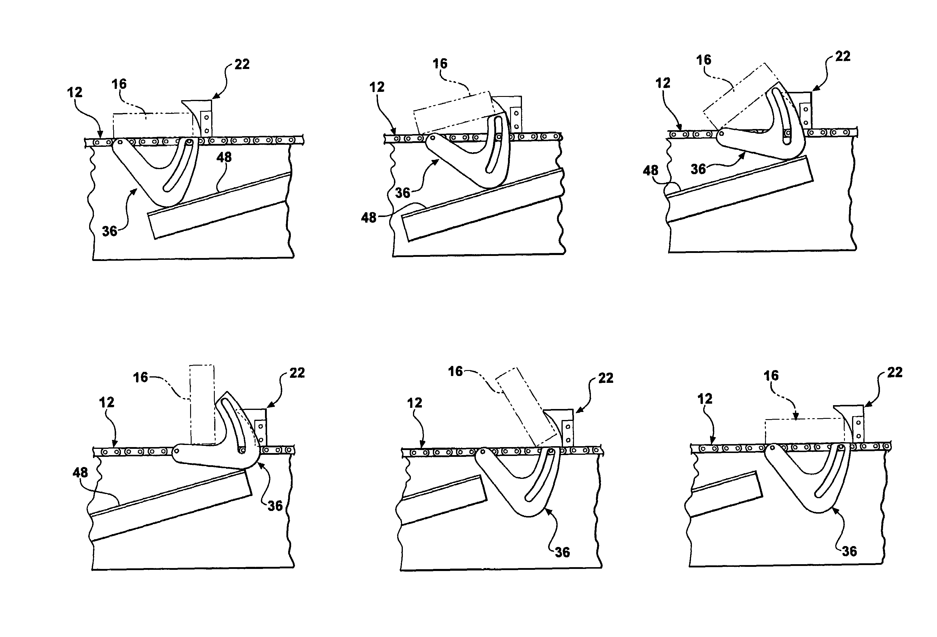
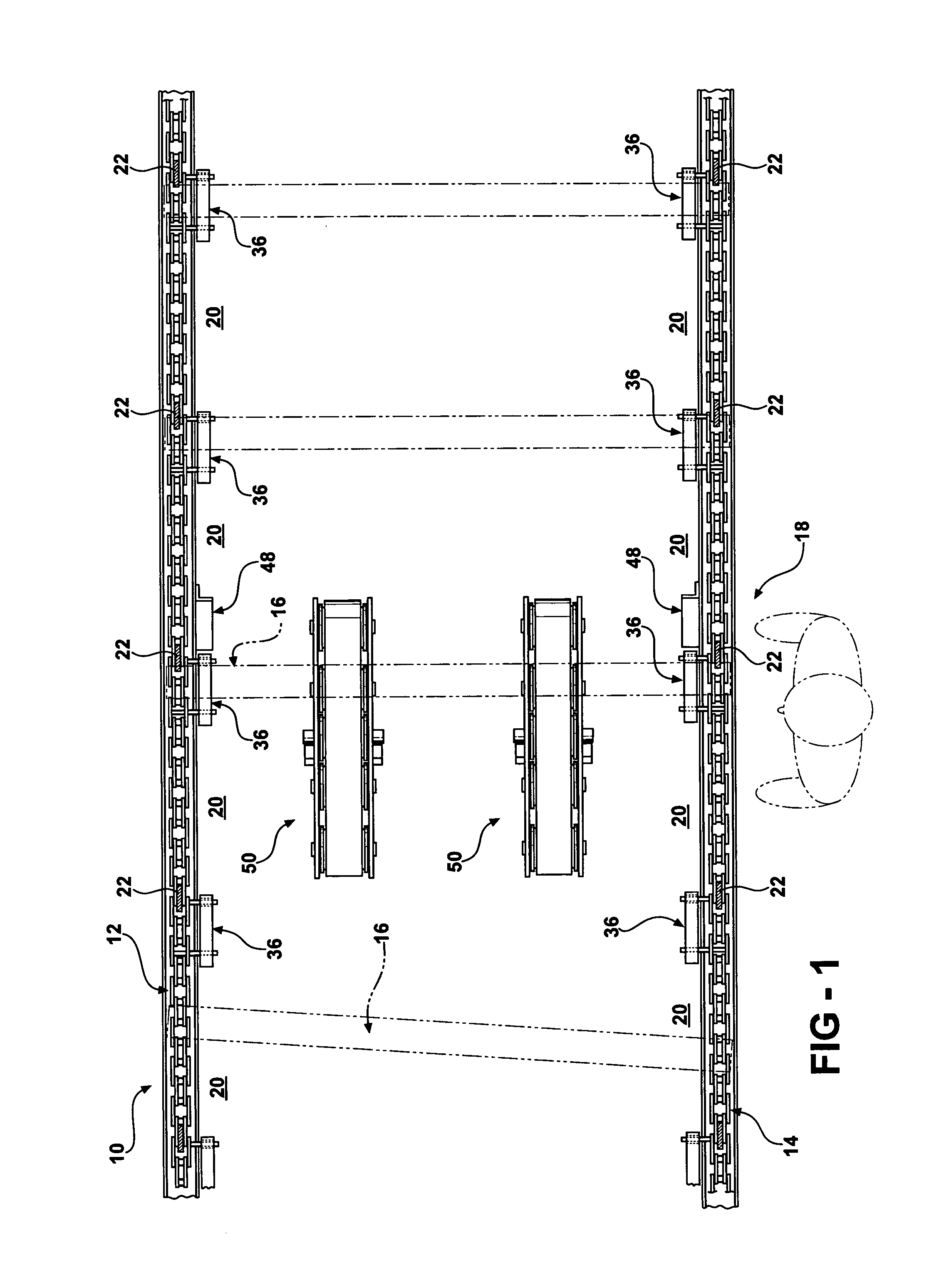
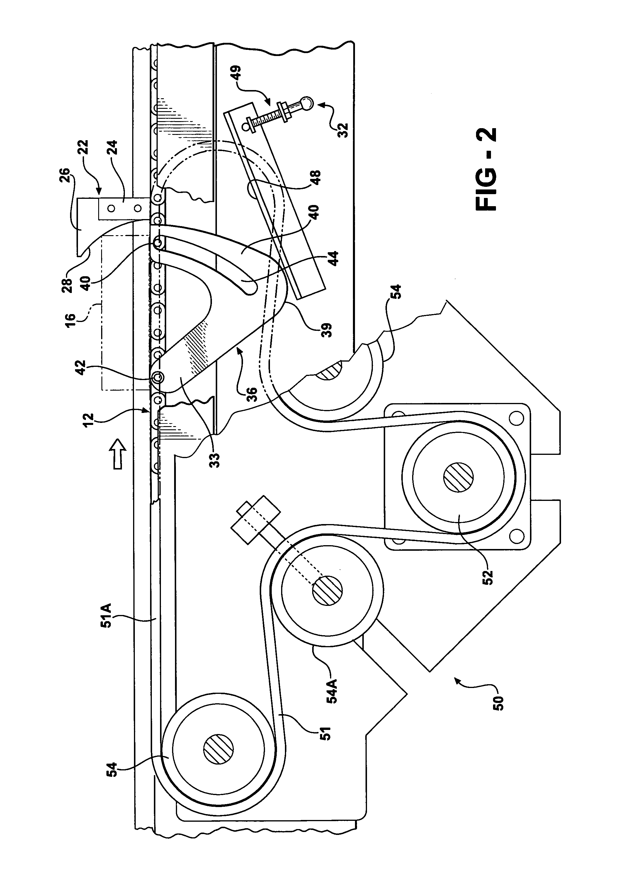
[0023]Referring to the drawings, FIG. 1 is an overhead view of a conveyor 10 including two recirculating conveyor chain loops 12, 14 advancing articles shown as pieces 16 of lumber or boards extending across the upper surface of the chain loops 12, 14 loaded into spaces 20 between a series of lugs 22 connected to the conveyor loops 12, 14. The pieces 16 are frictionally engaged by the conveyor chain loops 12, 14 and thereby advanced sideways to a turnover station 18 where a human grader may be in a position as indicated. The apparatus is usable in various other applicati...


PUM

PropertyMeasurementUnit
shapeaaaaaaaaaa
angleaaaaaaaaaa
speedaaaaaaaaaa

Abstract

A turnover apparatus and method for inverting articles such as lumber or board pieces being conveyed sideways on two or more conveyor chain loops in which each article is advanced on the conveyor chain loops by speed up belts engaging the underside of the articles to force a leading side against a pair of lugs mounted on a respective conveyor chain loop, the article thereafter flipped up to an on edge position by flipper arms also mounted on the conveyor chain loops which each engage an adjustable cam ramp at a turnover station, the article thereafter tipped over backward by being driven by the speed belts against an elevated overhung trailing edge on the lugs to complete the turnover. Optional pivoted let down elements may be arranged to engage the trailing side of the articles to controllably lower the same by motion induced by a second cam ramp at the turnover station.

Description

CROSS REFERENCE TO RELATED APPLICATIONS[0001]This application claims the benefit of U.S. provisional Ser. No. 60 / 430,767, filed Dec. 3, 2002.BACKGROUND OF THE INVENTION[0002]This invention concerns apparatus for turning over articles as they are being conveyed past a station. This may be done in order that an inspector is able to observe a reverse side of the article, as for example, board and lumber pieces conveyed sideways past a grader. Other conveyed articles such as doors, panels, etc., may need to be inverted for assembly or processing steps.[0003]For many years, human lumber grade sorters stood at inspection stations next to a board conveyor and manually turned over the pieces passing by the station.[0004]This manual operation was practical at the low speeds at which earlier conveyors operated, i.e., 40–50 pieces per minute.[0005]Subsequently, conveyors have been speeded up to 100 or more pieces per minute. At these rates, a turnover apparatus is necessitated in order that hu...

Claims


Application Information

Patent Timeline
Patent Type & Authority Patents(United States)
IPC IPC(8): B21B39/22B65G47/244B65G47/252B25J1/00B65G47/24
CPCB65G47/24B65G47/248B65G47/252B65G2201/0282
Inventor KAUPPILA, RICHARD W.HINTSALA, DANIEL L.
Owner KAUPPILA RICHARD W
Why Eureka
Try Eureka