Bobbin module of transformer

a transformer and bobbin technology, applied in the direction of transformer/inductance details, coils, electrical equipment, etc., can solve the problems of increasing mold cost, increasing the cost of material cost of tape, and increasing the time-consuming and difficult process of enclosing the bobbin, coil and the iron core with the tape, so as to reduce the cost of mold and reduce the cost of tape. , the effect of increasing the pressure resistan

Inactive Publication Date: 2006-12-26
DARFON ELECTRONICS CORP
View PDF7 Cites 19 Cited by
  • Summary
  • Abstract
  • Description
  • Claims
  • Application Information

AI Technical Summary

Benefits of technology

[0008]It is therefore an object of the invention to provide a bobbin module of transformer capable of decreasing mold cost and increasing pressure resistance. The invention forms two bobbins of identical structure by having the hooker and the indentation of a bobbin which are symmetric to each other be coupled together, not only making the assembly faster, but also achieving the positioning in x, y and z directions for assembly lest the separation of bobbin might occur when the conventional bobbin module receives an external force in the z direction. Besides, the invention requires only one set of mold. The manufacturer does not need to manufacture respective molds for the male bobbin mold and the female bobbin mold, largely decreasing the mold cost.
[0009]Furthermore, the invention achieves the object of fast positioning the bobbin and the base for assembly by using the design of engaging the fourth engaging blade of a bobbin with the first engaging blade of a base. The invention uses the second engaging blade and the third engaging blade to separate the two iron cores disposed in the first magnetic core receiving region and the second magnetic core receiving region from the coils of the primary coil and the secondary coil wound in the bobbin, substantially enhancing the pressure resistance of transformer and complying with the current trend in the design of enlarging the scale of the LCD panel and increasing the voltage of the lamp tube driving voltage.

Problems solved by technology

Thus, the mold cost will be increased.
However, the process of enclosing the bobbin, the coil and the iron core with the tape is very time-consuming and difficult, and the material cost for the tape is significant.
Since the conventional transformer whose bobbin, coil and iron core are enclosed by the tape has a poor performance in pressure resistance, the conventional transformer is difficult to meet the requirements of the current trend of enlarging the scale of LCD panel and increasing the voltage of the lamp tube driving voltage.

Method used


Image

  • Bobbin module of transformer
  • Bobbin module of transformer
  • Bobbin module of transformer

Examples


first embodiment

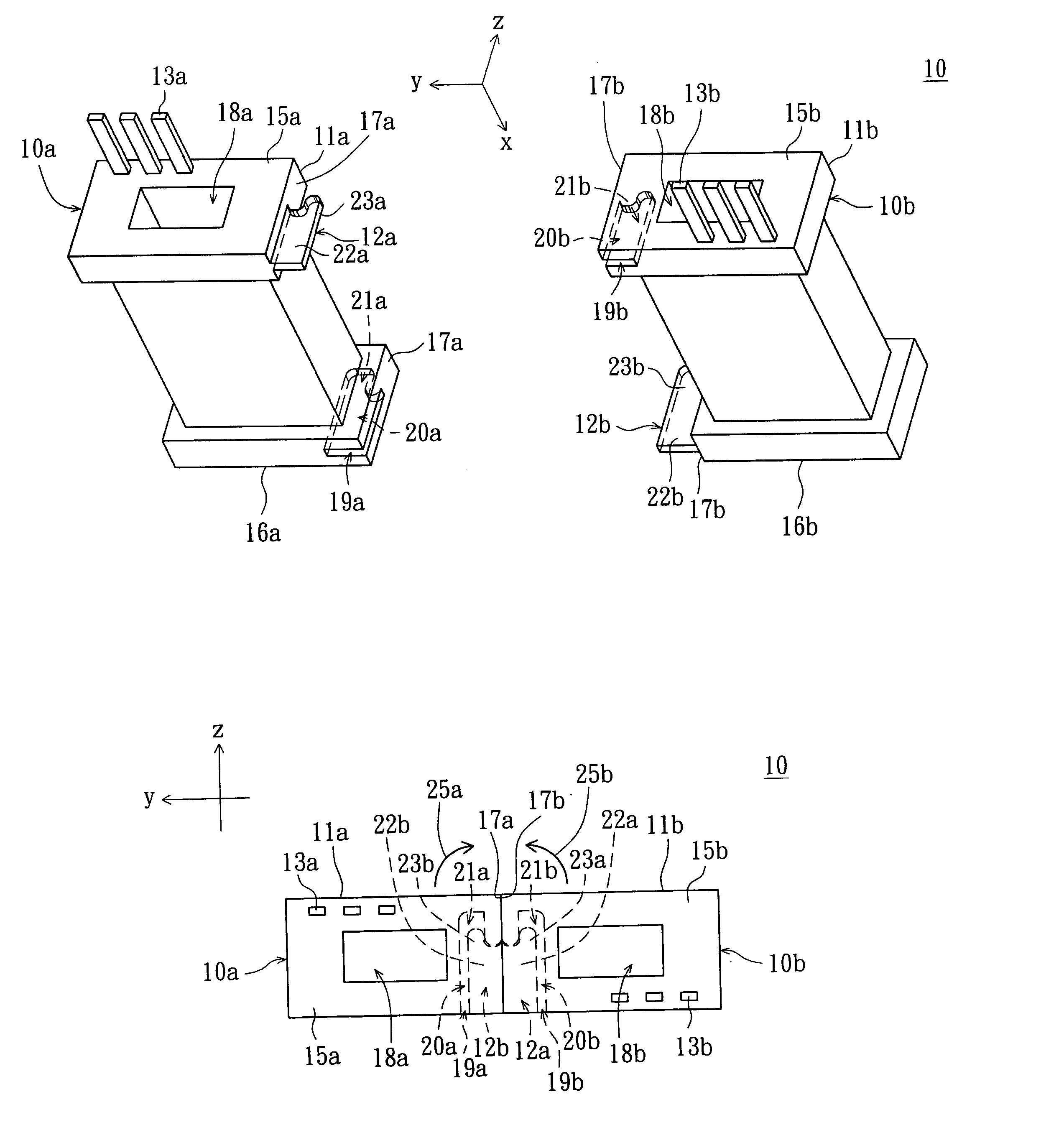
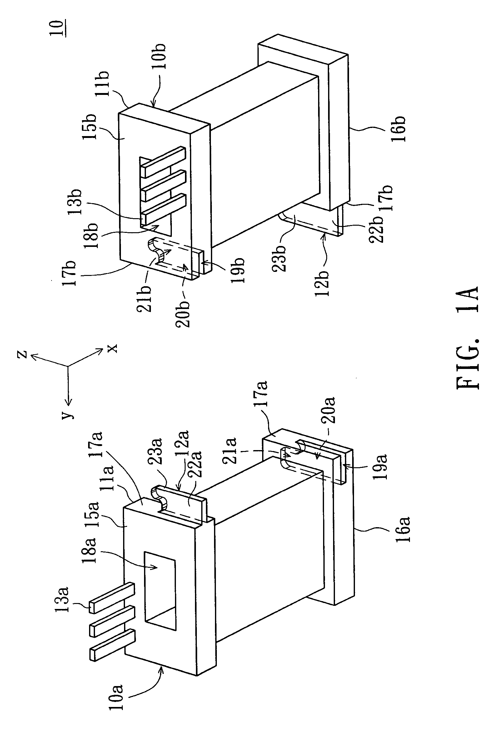
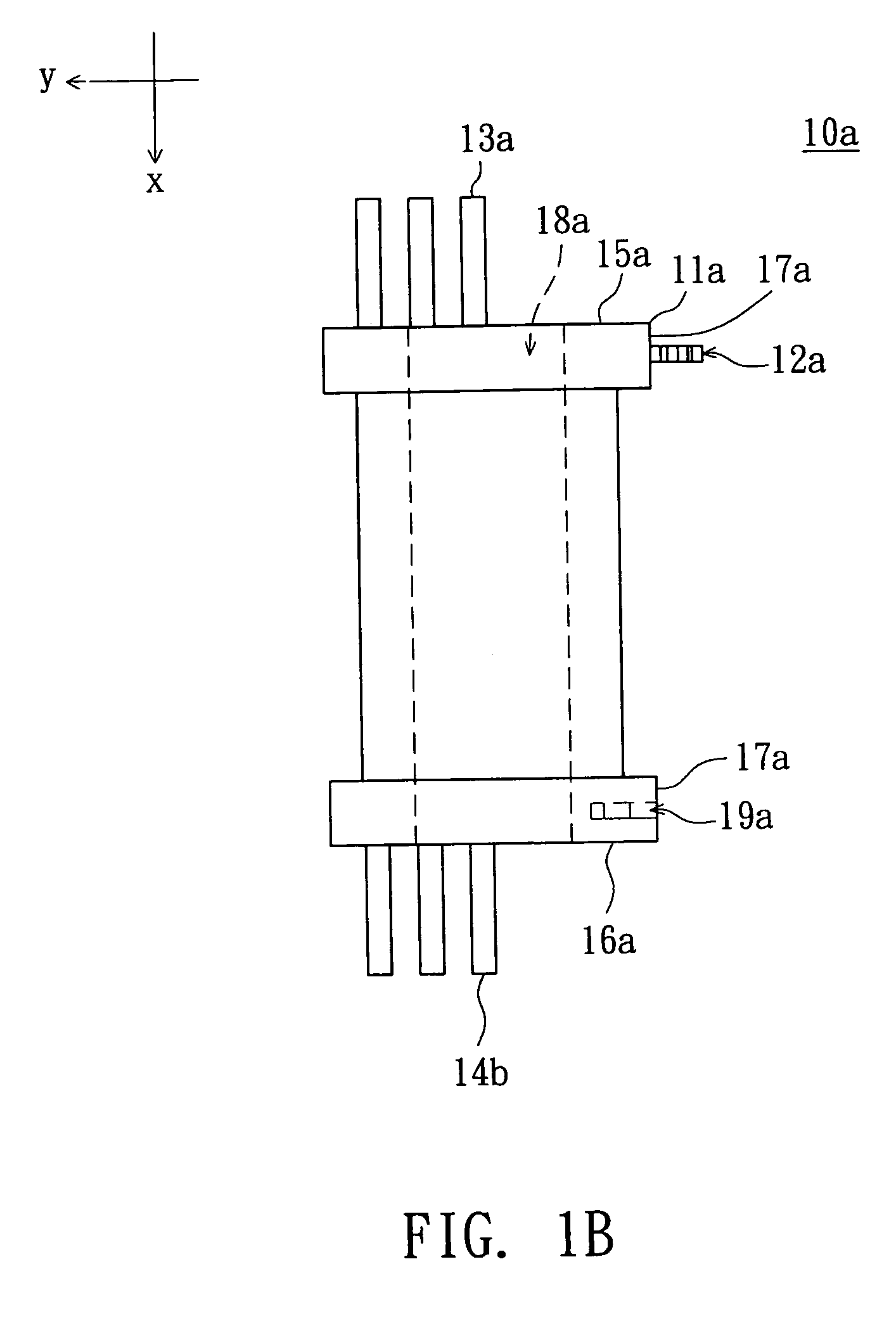
[0027]Referring to FIG. 1A, an exploded diagram of a bobbin module of transformer according to a first embodiment of the invention is illustrated. In FIG. 1A, the bobbin module of transformer 10 comprises two bobbins 10a and 10b. The bobbins 10a and 10b have the same structure and can be formed using the same bobbin mold. Thus, there is no need to manufacture respective molds for the male bobbin and the female bobbin, largely decreasing the mold cost. As shown in FIG. 1B, the bobbin 10a comprises a body 11a, a hooker 12a and an indentation 19a. The body 11a has a lateral surface 17a on which the hooker 12a and the indentation 19a are disposed. Similarly, the bobbin 10b comprises a body 11b, a hooker 12b and an indentation 19b. The body 11b has a lateral surface 17b on which the hooker 12b and the indentation 19b are disposed. When the bobbins 10a and 10b are combined together, the hooker 12a and the indentation 19a of the bobbin 10a are respectively engaged with the indentation 19b ...

second embodiment

[0033]Please refer to FIGS. 2A˜2F at the same time. FIG. 2A is an exploded top view of a bobbin module of transformer according to a second embodiment of the invention. FIG. 2B is top view of a base of FIG. 2A. FIG. 2C is an upward view of the bobbin of FIG. 2A. FIG. 2D is a top view of the bobbin of FIG. 2A. FIG. 2E is a cross-sectional diagram of assembly of the bobbin module of transformer according to the second embodiment of the invention. FIG. 2F is a top view of assembly of the bobbin module of transformer according to the second embodiment of the invention. In FIG. 2A, the bobbin module of transformer 20 comprises a base 21 and a bobbin 22. The bobbin 22 is engaged with the base 21 to be disposed on the base 21 As shown in FIG. 2B, the base 21 has a fillister 23 whose bottom 23a has a first engaging blade 24a, a second engaging blade 24b parallel to the first engaging blade 24a, and a third engaging blade 24c disposed thereon. The first engaging blade 24a is perpendicular to...

third embodiment

[0038]Please refer to FIGS. 3A˜3D. FIG. 3A is a part of cross-sectional exploded diagram of a bobbin module of transformer according toad third embodiment of the invention. FIG. 3B is an upward view of a lift cover of FIG. 3A. FIG. 3C illustrates the assembly of the lift cover of FIG. 3B and the bobbin of FIG. 2C. FIG. 3D is a cross-sectional assembly diagram of the bobbin module of transformer according to the third embodiment of the invention. The bobbin module of transformer 30 of the present embodiment of the invention differs with the bobbin module of transformer 20 of the second embodiment in having a lift cover 31. As for other similar components, the same reference numbers are used and are not repeated here. In FIGS. 3A˜3B, the lift cover 31 comprises a body 31a, a fifth engaging blade 32a, a sixth engaging blade 32b and a seventh engaging blade 32c parallel to the sixth engaging blade 32b. The body 31a has a number of openings 31b and 31c. The fifth engaging blade 32a, the ...


PUM

PropertyMeasurementUnit
contained angleaaaaaaaaaa
pressure resistanceaaaaaaaaaa

Abstract

A bobbin module of transformer is provided. The bobbin module includes two bobbins. Each of the bobbins comprises a body, an indentation and a hooker. The body has a lateral surface on which the indentation and the hooker are disposed. The hooker and the indentation of the bobbin are respectively engaged with the hooker and the indentation of the other bobbin so that the two bobbins are combined together.

Description

[0001]This application claims the benefit of Taiwan application Ser. No. 94106147, filed Mar. 1, 2005, the subject matter of which is incorporated herein by reference.BACKGROUND OF THE INVENTION[0002]1. Field of the Invention[0003]The invention relates in general to a bobbin of transformer, and more particularly to a bobbin module of transformer capable of decreasing mold cost and increasing pressure resistance.[0004]2. Description of the Related Art[0005]With the popularity of multi-media products, the application of liquid crystal display (LCD) such as computer monitor and LCD TV is also becoming more and more popular. Typically, the LCD adopts slim and high efficient lamp tube driving system as the backlight, so that the thickness is reduced and that the display quality is improved. The lamp tube driving system of an LCD mainly consists of a cold cathode fluorescent lamp (CCFL) discharge lamp tube and a transformer used for driving the CCFL. Under the current trend of large-scale...

Claims


Application Information

Patent Timeline
Patent Type & Authority Patents(United States)
IPC IPC(8): H01F27/30
CPCH01F5/02H01F27/303H01F2005/022H01F2027/297
Inventor HSUEH, CHING-FUCHEN, WEN-HSIENHSU, WAN-CHIN
Owner DARFON ELECTRONICS CORP
Why Eureka
Try Eureka