Thrust vector control system for a plug nozzle rocket engine

a technology of vector control and thruster, which is applied in the direction of vessel construction, marine propulsion, aircraft navigation control, etc., can solve the problems of high power required to achieve rapid response, heavy, complex, and difficult to reorient exhaust flow from a conventional annular plug nozzle throa

Inactive Publication Date: 2007-01-02
AEROJET ROCKETDYNE INC
View PDF13 Cites 19 Cited by
  • Summary
  • Abstract
  • Description
  • Claims
  • Application Information

AI Technical Summary

Problems solved by technology

The exhaust flow from a conventional annular plug nozzle throat is largely symmetrical and not easily redirected for the purpose of altering the thrust vector to control attitude or direction of the vehicle on which the engine is mounted.
These mechanisms are exposed to large forces, require high power to achieve rapid response, are heavy, complex, and costly.
This system is complicated and expensive.

Method used


Image

  • Thrust vector control system for a plug nozzle rocket engine
  • Thrust vector control system for a plug nozzle rocket engine
  • Thrust vector control system for a plug nozzle rocket engine

Examples


Embodiment Construction

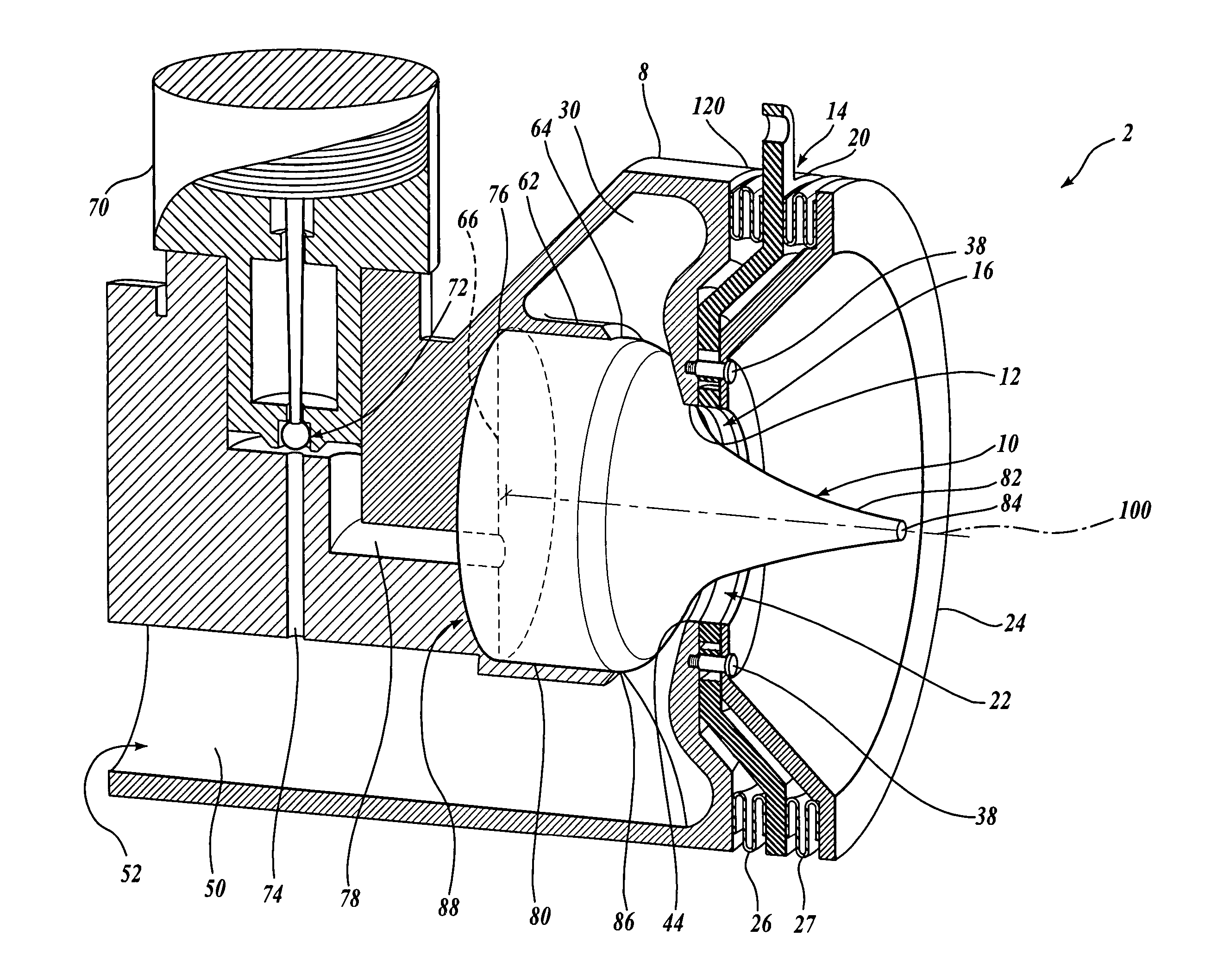
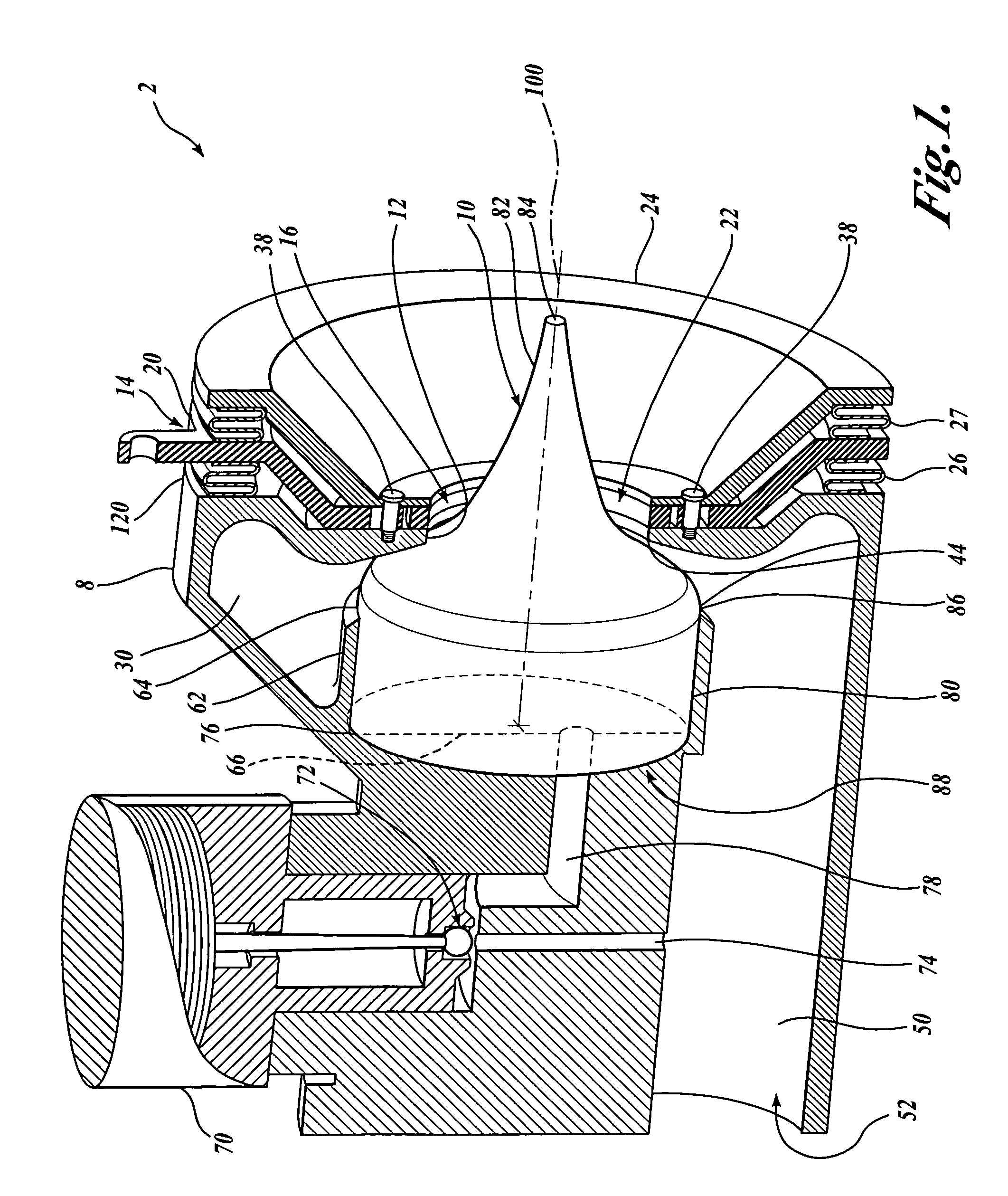
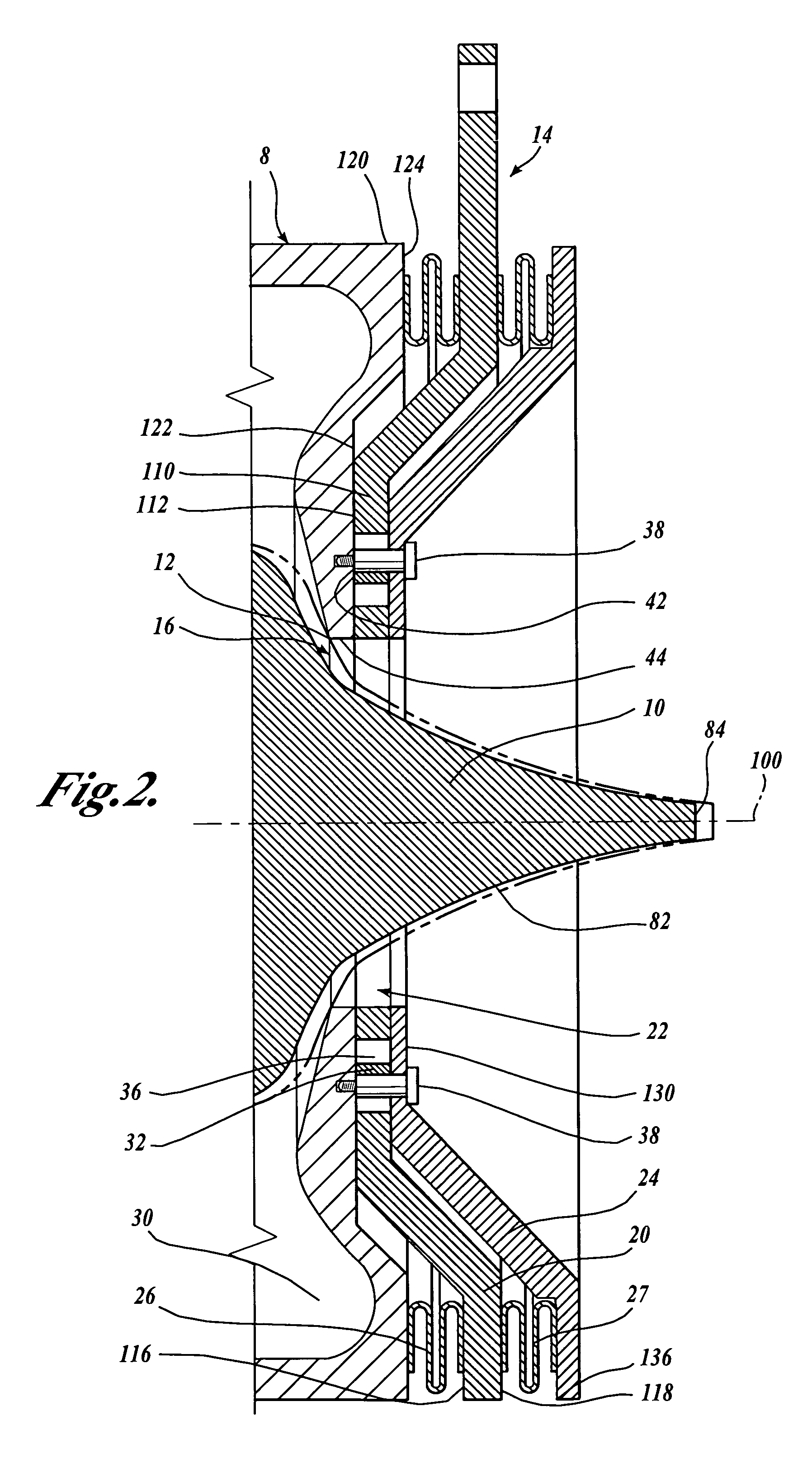
[0025]Referring to FIGS. 1 and 2, a plug nozzle rocket engine 2 includes a housing 8 having a plug nozzle throat 12 located at the rearward end 120 of the housing 8. Located centrally in the housing 8 is a cylindrical chamber 62 having an open rearward end 64 and a closed forward end 66. Surrounding the cylindrical chamber 62 is an annular plenum cavity 30. The plenum cavity 30 has an annular exit, or nozzle throat 12, positioned rearwardly of the rearward end 64 of the cyclindral chamber 62. The nozzle throat 12 begins at an annular rim 44 of the plenum cavity 30 and is the outlet for gas (or exhaust) from the housing 8. The nozzle throat 12 is annular in configuration and is oriented perpendicularly to the longitudinal axis 100 of the cylindrical chamber 62. The nozzle throat 12 is located concentrically about the longitudinal axis 100 of the cylindrical chamber 62. The nozzle throat 12 has a diameter less than the diameter of the cyclindral chamber 62. A propellant or gas supply ...


PUM


Abstract

A thrust vector control system for a plug nozzle rocket engine for propelling and maneuvering a vehicle is disclosed. The plug nozzle rocket engine includes a housing having a nozzle throat, a plug disposed within the housing and positioned within the nozzle throat to define a space between the plug and the nozzle throat, and a thrust diverter moveably disposed relative to the housing to define an asymmetric pressure distribution along the plug for thrust-vectoring. In one embodiment, the thrust diverter is normally biased to a non-thrust-vectoring position, but is moveable in a plane substantially perpendicular to an axis extending longitudinally through the plug.

Description

FIELD OF THE INVENTION[0001]This invention relates to thrust vector control systems for thrusters used for propelling and maneuvering vehicles, and more specifically to thrust vector control systems for plug nozzle rocket engines.BACKGROUND OF THE INVENTION[0002]Plug nozzle rocket engines are common engines in the field of rocket, missile, and space vehicle propulsion. The exhaust flow from a conventional annular plug nozzle throat is largely symmetrical and not easily redirected for the purpose of altering the thrust vector to control attitude or direction of the vehicle on which the engine is mounted.[0003]Traditionally, angular displacement of a thrust vector has required angular displacement of the entire rocket engine. For example, one type of thrust vector control system is a gimbaled thruster. The gimbaled thruster moves about a point of rotation relative to the vehicle on which it is mounted to redirect the thrust vector of the vehicle. This system requires precise gimballin...

Claims


Application Information

Patent Timeline
Patent Type & Authority Patents(United States)
IPC IPC(8): F02K9/90F02K1/78F02K9/86F02K9/97
CPCF02K9/86F02K9/978F05D2250/27F05D2250/26F05D2250/232
Inventor SOTA, JR., CHARLES G.CALLIS, GEORGE J.MASSE, ROBERT K.
Owner AEROJET ROCKETDYNE INC
Why Eureka
Try Eureka