Antenna-mounted sign for vehicles

a technology for vehicles and antennas, applied in the field of vehicles, can solve the problems of inability to mount flags or pennants on vehicle antennas, inconvenient retractable antennas, and inability to achieve feats, etc., and achieve the effect of effective balancing the wing sections

Inactive Publication Date: 2007-01-02
DAVIS JOHN W J
View PDF24 Cites 14 Cited by
  • Summary
  • Abstract
  • Description
  • Claims
  • Application Information

AI Technical Summary

Benefits of technology

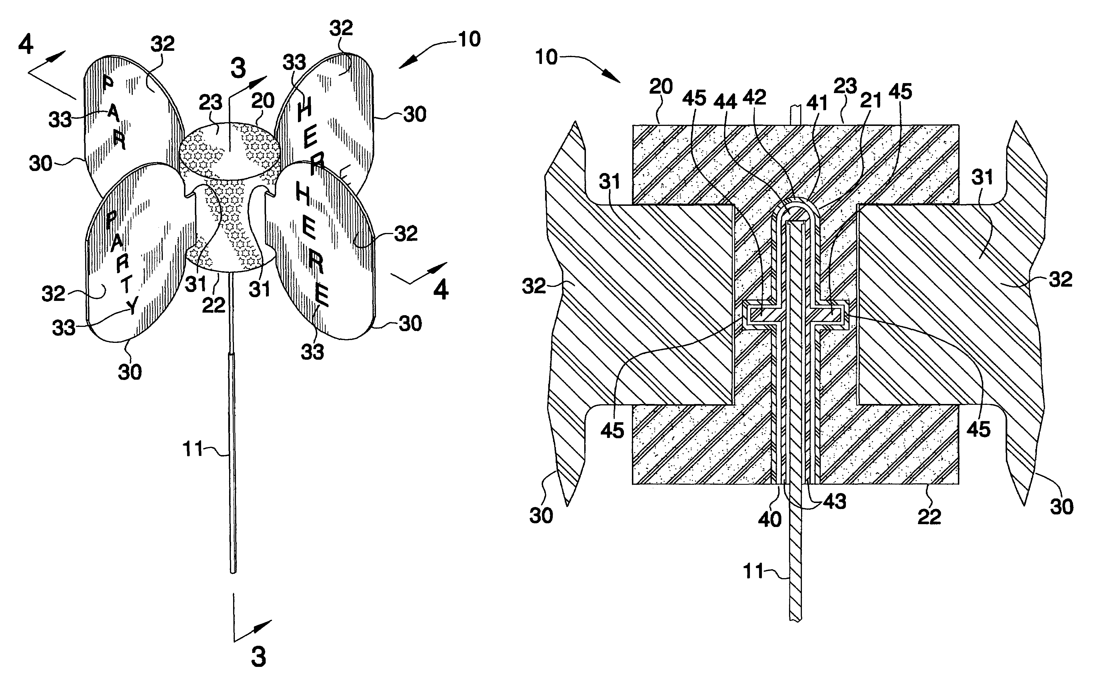
[0014]The present invention further includes a mechanism for positioning the apparatus about the vehicle antenna such that the anchor section and the wing sections can conveniently freely rotate in clockwise and counter clockwise directions during traveling conditions. Such an apparatus positioning mechanism is disposed within the anchor section and is suitably sized and shaped so that the anchor section can advantageously be maintained at a substantially stable position during operating conditions. The apparatus positioning mechanism is formed from non-corrosive material.
[0015]Such an apparatus positioning mechanism preferably further includes a rigid and stationary insert directly nested within an interior wall of the sleeve. The insert has an arcuate top end portion situated above a center of mass of the anchor section for effectively balancing the wing sections about the vehicle antenna. A rigid and mobile insert is permanently intercalated within the sleeve and directly engageable with the stationary insert in such a manner that the mobile insert can conveniently freely rotate within the sleeve and cause the anchor and wing sections to contemporaneously rotate therewith. Such a mobile insert has a closed top end portion provided with an arcuate shape for cooperating with the arcuate top end portion of the stationary insert during rotational movements.
[0016]Each of the stationary and mobile inserts preferably have a monolithically formed flange portion protruding outwardly away therefrom and radially extending thereabout from the axis. Such flange portions advantageously restrict the mobile insert from disengaging the stationary insert during traveling conditions.

Problems solved by technology

Unfortunately, the mounting of such flags or pennants on vehicle antennas is limited to fixed, vertical antennas and is not suitable for the retractable antennas or the angled non-vertical antennas.
As a consequence of the damage likely to be caused to such flags or pennants in a commercial car wash, for instance, they should be readily removable to avoid such damage, a feat not possible with those flags currently found in the prior art.
Thus, a flag made of inexpensive cotton material may disintegrate rapidly on a car traveling at 65 miles an hour.
It has also been noted that violent wind action, even at lower speeds, tends to whip the flag around so much that it is difficult to discern whatever is imprinted on the flag or pennant.

Method used


Image

  • Antenna-mounted sign for vehicles
  • Antenna-mounted sign for vehicles
  • Antenna-mounted sign for vehicles

Examples


Embodiment Construction

[0025]The present invention will now be described more fully hereinafter with reference to the accompanying drawings, in which a preferred embodiment of the invention is shown. This invention may, however, be embodied in many different forms and should not be construed as limited to the embodiment set forth herein. Rather, this embodiment is provided so that this application will be thorough and complete, and will fully convey the true scope of the invention to those skilled in the art. Like numbers refer to like elements throughout the figures.

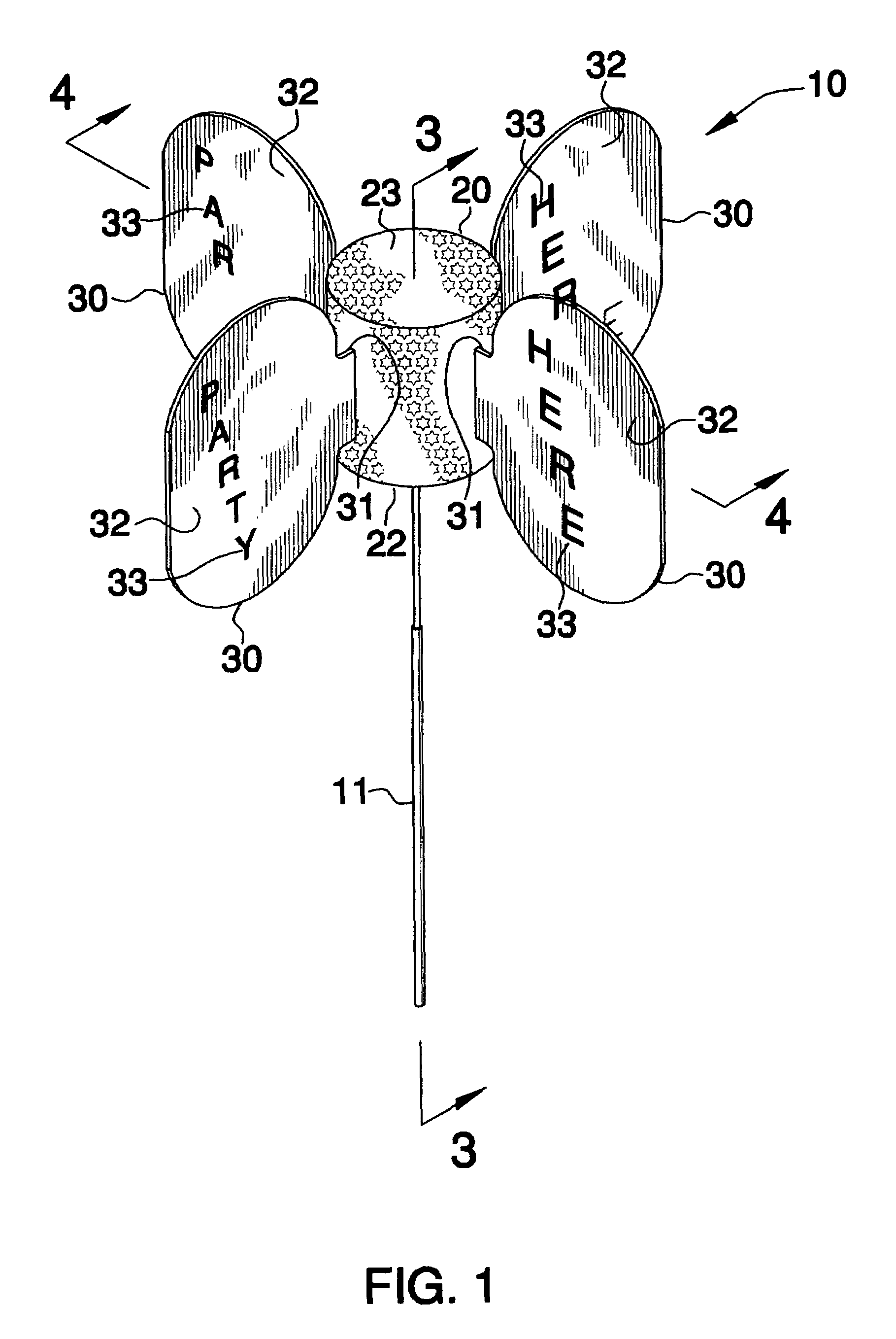
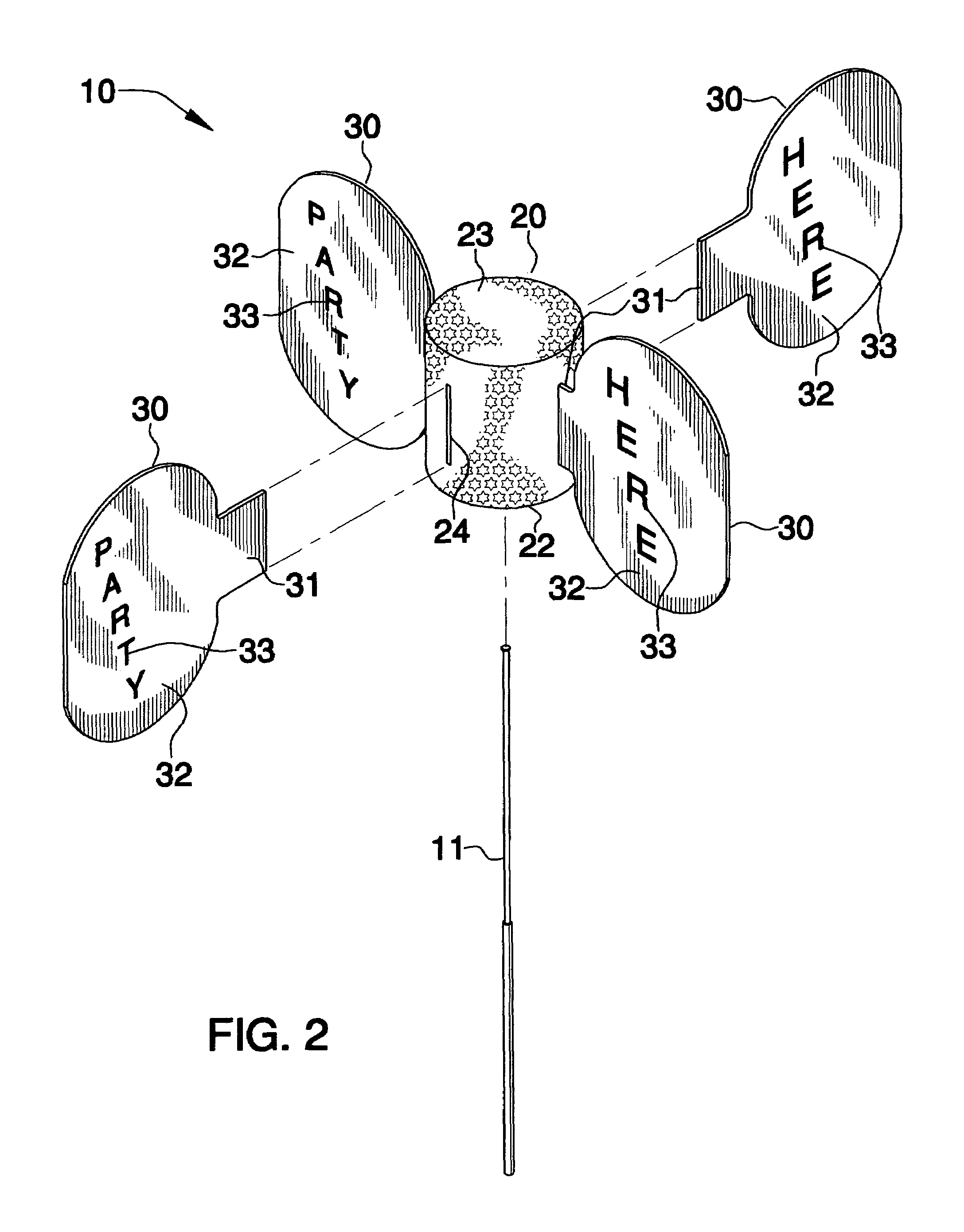
[0026]The apparatus of this invention is referred to generally in FIGS. 1–5 by the reference numeral 10 and is intended to provide an antenna-mounted sign for vehicles. It should be understood that the apparatus 10 may be mounted on many different types of rod structures and should not be limited in use to only vehicle antennas.

[0027]Referring initially to FIGS. 1 and 3, the apparatus 10 includes an anchor section 20 formed from STYROFOAM (po...


PUM


Abstract

An apparatus conjoinable to a vehicle antenna includes an anchor section formed from STYROFOAM (polystyrene) and provided with a vertically registered sleeve extending along a longitudinal axis. The sleeve extends upwardly from a bottom surface of the anchor and terminates subjacent to a top surface thereof. Coextensively shaped wing sections are conjoinable with the anchor section and equidistantly spaced about an outer surface thereof. A mechanism is included for positioning the apparatus about the vehicle antenna and allows for free rotation thereof in the wind. The apparatus positioning mechanism is disposed within the anchor section and is sized and shaped so that the anchor section can be maintained at a stable position during operating conditions. The apparatus positioning mechanism is formed from non-corrosive material.

Description

CROSS REFERENCE TO RELATED APPLICATIONS[0001]Not Applicable.STATEMENT REGARDING FEDERALLY SPONSORED RESEARCH OR DEVELOPMENT[0002]Not Applicable.REFERENCE TO A MICROFICHE APPENDIX[0003]Not Applicable.BACKGROUND OF THE INVENTION[0004]1. Technical Field[0005]This invention relates to signs for vehicles and, more particularly, to an antenna-mounted sign for vehicles.[0006]2. Prior Art[0007]The invention relates generally to flags and pennants that are mounted temporarily or permanently to the radio antenna of an automobile or truck. These flags or pennants have typically been composed of either a flexible fabric material such as cloth or light plastic or of a substantially rigid material, usually a plastic material. The location on the automobile radio antenna for the mounting of a flag or pennant is preferred because this location provides a prominent, elevated position, which is readily visible by the public as the automobile or truck passes by on the street. Unfortunately, the mounti...

Claims


Application Information

Patent Timeline
Patent Type & Authority Patents(United States)
IPC IPC(8): A63H33/40
CPCB60R13/00A63H33/40
Inventor DAVIS, JOHN W. J.
Owner DAVIS JOHN W J
Why Eureka
Try Eureka