Fastening tool wire guide

a technology of fastener and wire guide, which is applied in the direction of stapling tools, manufacturing tools, electrical equipment, etc., can solve the problems of complex devices, difficult use, and/or compact devices, and achieve the effect of convenient operation and easy placement into a stable position in the tool

Active Publication Date: 2018-07-12
WORKTOOLS
View PDF11 Cites 2 Cited by
  • Summary
  • Abstract
  • Description
  • Claims
  • Application Information

AI Technical Summary

Benefits of technology

[0003]In an exemplary embodiment of the present invention, an extendible wire guide is slidably fitted at the front of a staple gun tool housing. A lever switch or similar operating device is linked to the wire guide to enable the wire guide to be deployed or retracted. The lever switch includes an up and a down position corresponding to a retracted and an extended position of the wire guide. In a preferred embodiment, the wire guide is immediately adjacent to, and in sliding contact with, a striker element. The wire guide is resiliently biased, preferably toward the retracted position. The lever switch preferably acts on the wire guide through a cam action on an upper edge or equivalent feature of the wire guide. The cam action operates against the bias on the wire guide. A bias spring is preloaded in a subassembly of the wire guide and bias spring whereby the subassembly is easily placed into a stable position in the tool. The lever switch presents a large feature that is easy to operate.

Problems solved by technology

However, such devices are either complex, hard to use, and / or not compact when installed within or to a tacker device.

Method used


Image

  • Fastening tool wire guide
  • Fastening tool wire guide
  • Fastening tool wire guide

Examples


Embodiment Construction

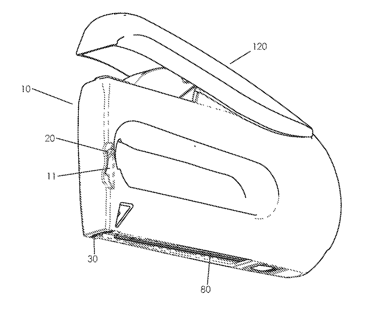
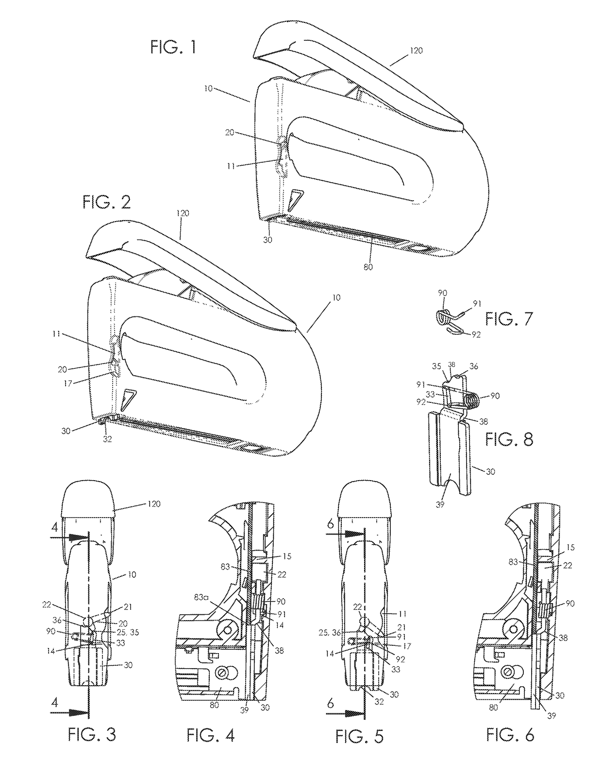
[0017]The present invention in a preferred embodiment is directed to an extendible wire guide that is slidably fitted at the front of a staple gun tool housing. In the drawing figures, an exemplary, staple gun or tacker tool is shown. As illustrated, it is a forward action tacker wherein handle 120 is at or near a top of the housing hinged at a rear of the tool, toward the right in FIG. 1, and pressed near a front, left in FIG. 1. Fasteners are guided upon or by fastener guide track 80 located along a lower portion or bottom of the tool. The staple or other fastener exits at the forward location of wire guide 30. The present wire guide may be fitted to a rear action tacker wherein the handle is hinged at a front and pressed rearward of the front.

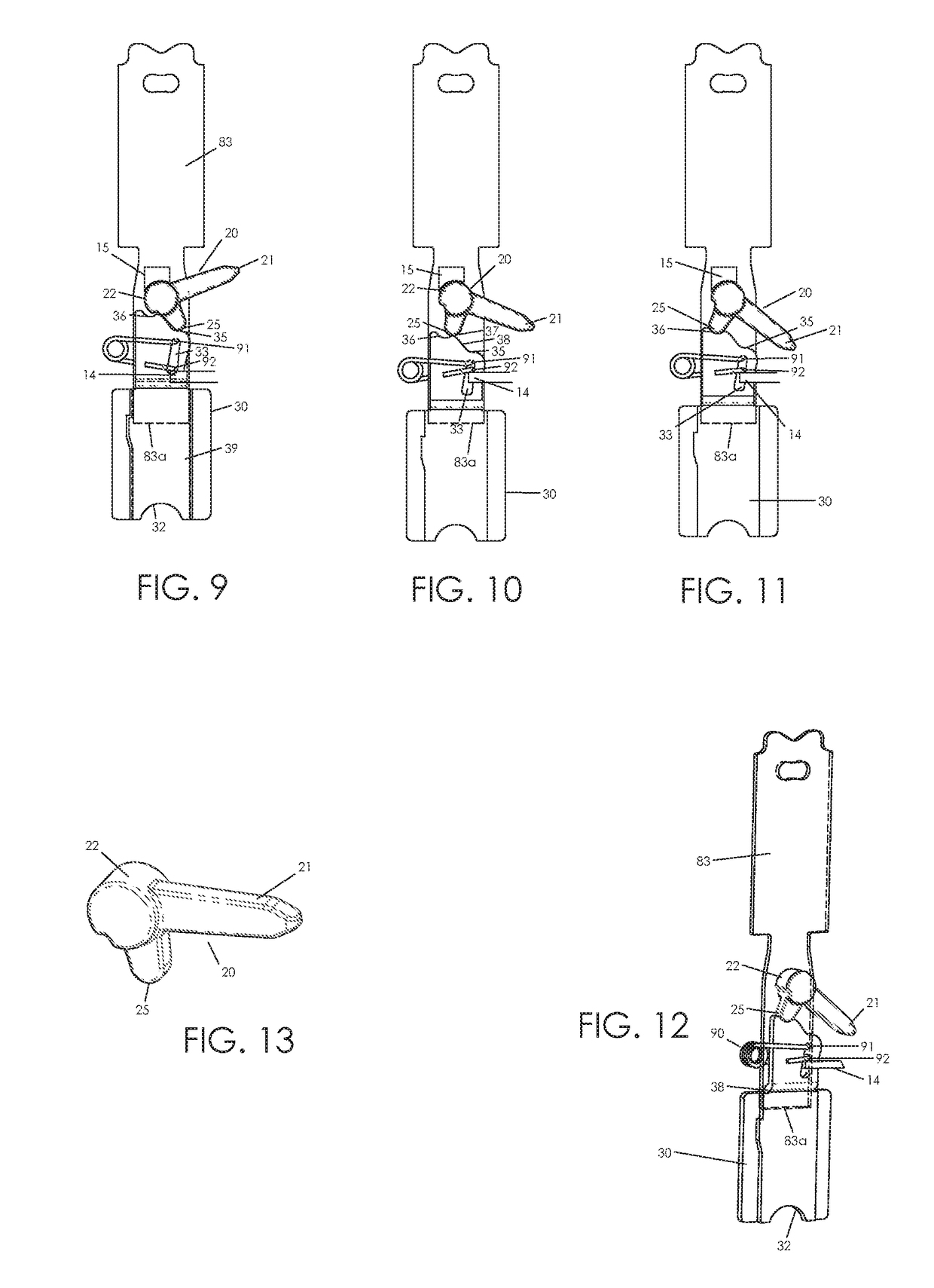
[0018]In FIGS. 1, 3, and 9, wire guide 30 is stowed, being preferably substantially flush with a bottom of housing 10. Lever switch 20 is in a corresponding stowed position, being at a top or upper termination of slot 11 as shown. The lever ...


PUM


Abstract

An extendible wire guide is slidably fitted at the front of a staple gun tool housing. An easily operated lever switch is linked to the wire guide to enable the wire guide to be deployed or retracted. The lever switch includes an up and a down position corresponding to a retracted and an extended position of the wire guide. The wire guide is resiliently biased, preferably toward the retracted position. The lever switch acts on the wire guide against the bias through a cam action on an upper edge of the wire guide. A bias spring is preloaded in a subassembly of the wire guide and bias spring for simplified final assembly.

Description

FIELD OF THE INVENTION[0001]The present invention relates to fastener driving tools. More precisely, the present invention relates to improvements in the operation of fastening wires by stapling.BACKGROUND OF THE INVENTION[0002]Staple guns and other tacker tools are known for fastening paper, cardboard, or similar thin materials to wood or other substrates. An additional application for staple guns is to hold electrical wires or similar items in place. The staple is installed over and around the wire. Typically staple guns are effective for only one or the other application. Single purpose wire staplers have a permanent notched extension downward from the front end to position the staple over the wire. This feature, however, prevents the staple from seating flush when used for ordinary materials. Tackers with a built-in wire guide are known. However, such devices are either complex, hard to use, and / or not compact when installed within or to a tacker device.SUMMARY OF THE INVENTION[...

Claims


Application Information

Patent Timeline
Patent Type & Authority Applications(United States)
IPC IPC(8): B25C5/06H02G3/30B25C5/11
CPCB25C5/06B25C5/11H02G3/30
Inventor MARKS, JOEL S.
Owner WORKTOOLS
Why Eureka
Try Eureka