Supercharge Your Innovation With Domain-Expert AI Agents!

Coolant regulating system for tractor trailers

a technology for tractor trailers and coolant, applied in the direction of machines/engines, mechanical equipment, transportation and packaging, etc., can solve the problems of truck drivers stranded, inopportune times, and inability to practice, so as to reduce the likelihood of coolant contamination

Inactive Publication Date: 2007-01-02
CRAIG STEPHEN H
View PDF6 Cites 8 Cited by
  • Summary
  • Abstract
  • Description
  • Claims
  • Application Information

AI Technical Summary

Benefits of technology

"The present invention is a coolant regulating system for tractor trailer tanks that separates coolants and reduces the likelihood of coolant contamination between tractor engines and associated trailers. The system includes a control switch for operating and non-operating modes, a heat transfer mechanism with a housing and inlet / outlet ports, and a mechanism for controlling the flow rate of the second coolant. The system also includes a reservoir for replenishing the second coolant and a one-way air valve to reduce internal air pressure. The technical effects of the invention include improved cooling efficiency, reduced likelihood of coolant contamination, and improved operational performance of tractor trailer tanks."

Problems solved by technology

This practice, however, is not desirable, since cross-contamination occurs between antifreeze entering from the trailer and antifreeze entering from the truck's engine.
Such cross-contamination can lead to serious engine troubles that are costly to repair and can leave a truck driver stranded at inopportune times. The integrated cooling system also tends to use antifreeze much more rapidly than in trucks that are only required to cool the engine.

Method used


Image

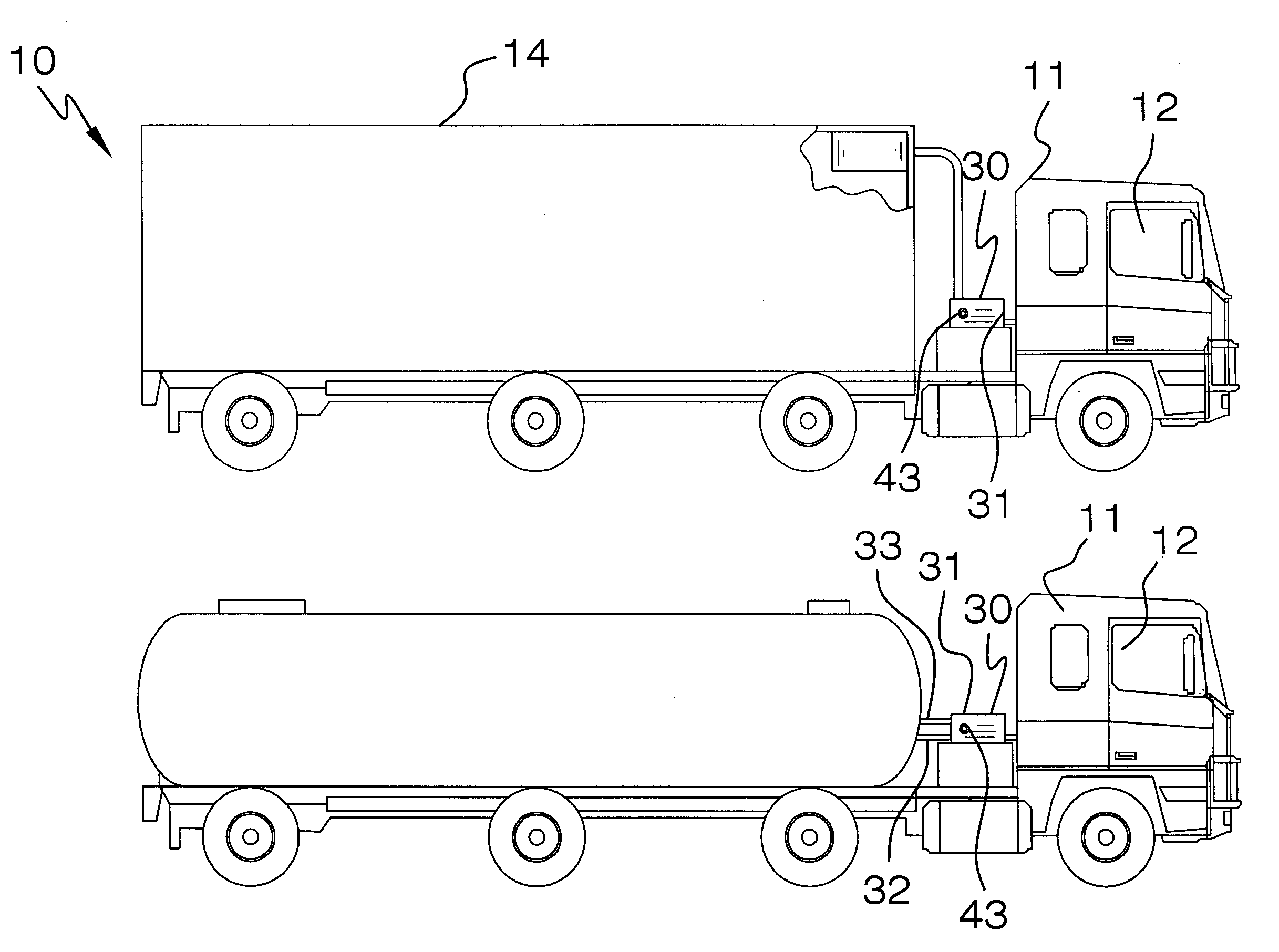
  • Coolant regulating system for tractor trailers
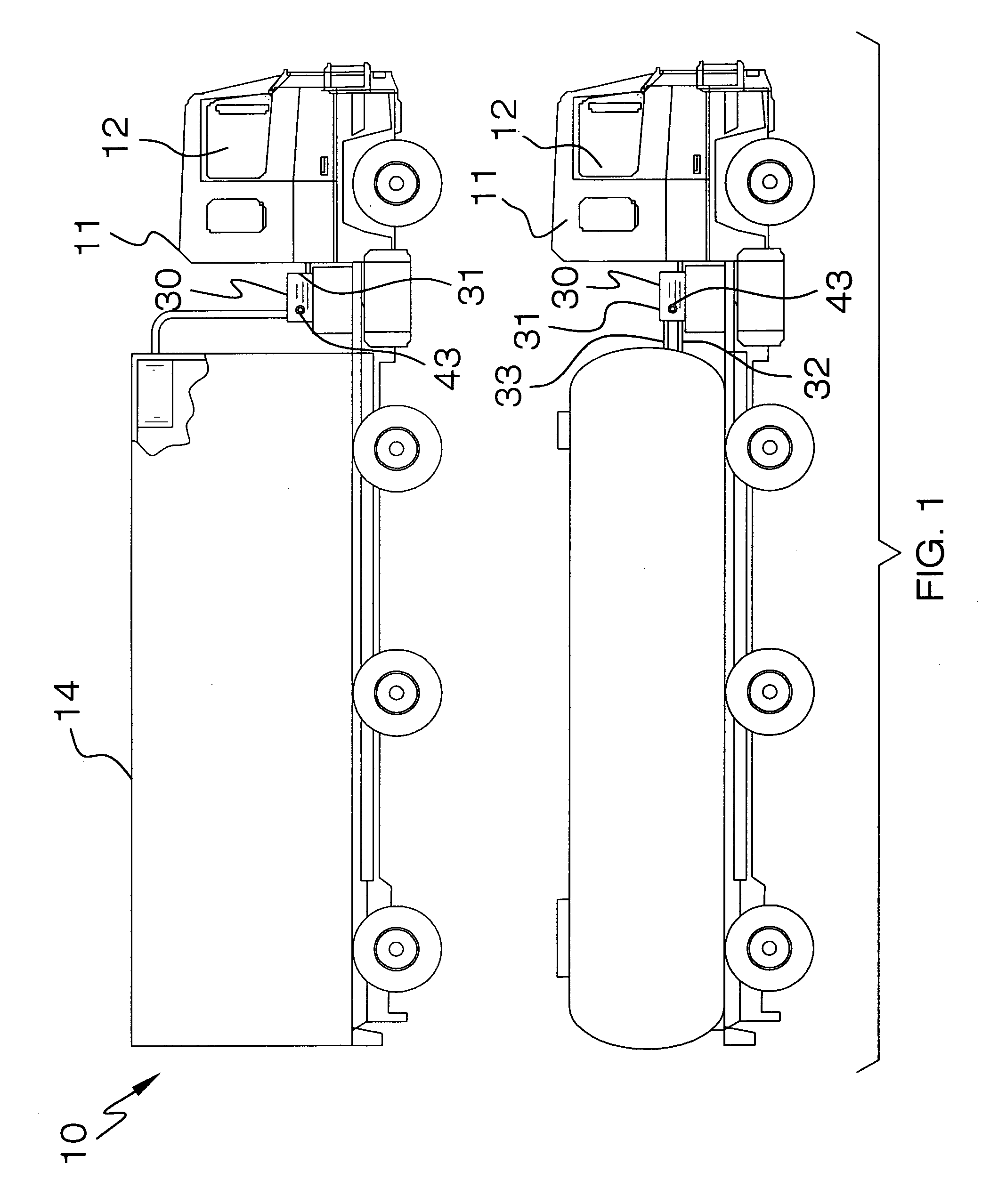
  • Coolant regulating system for tractor trailers
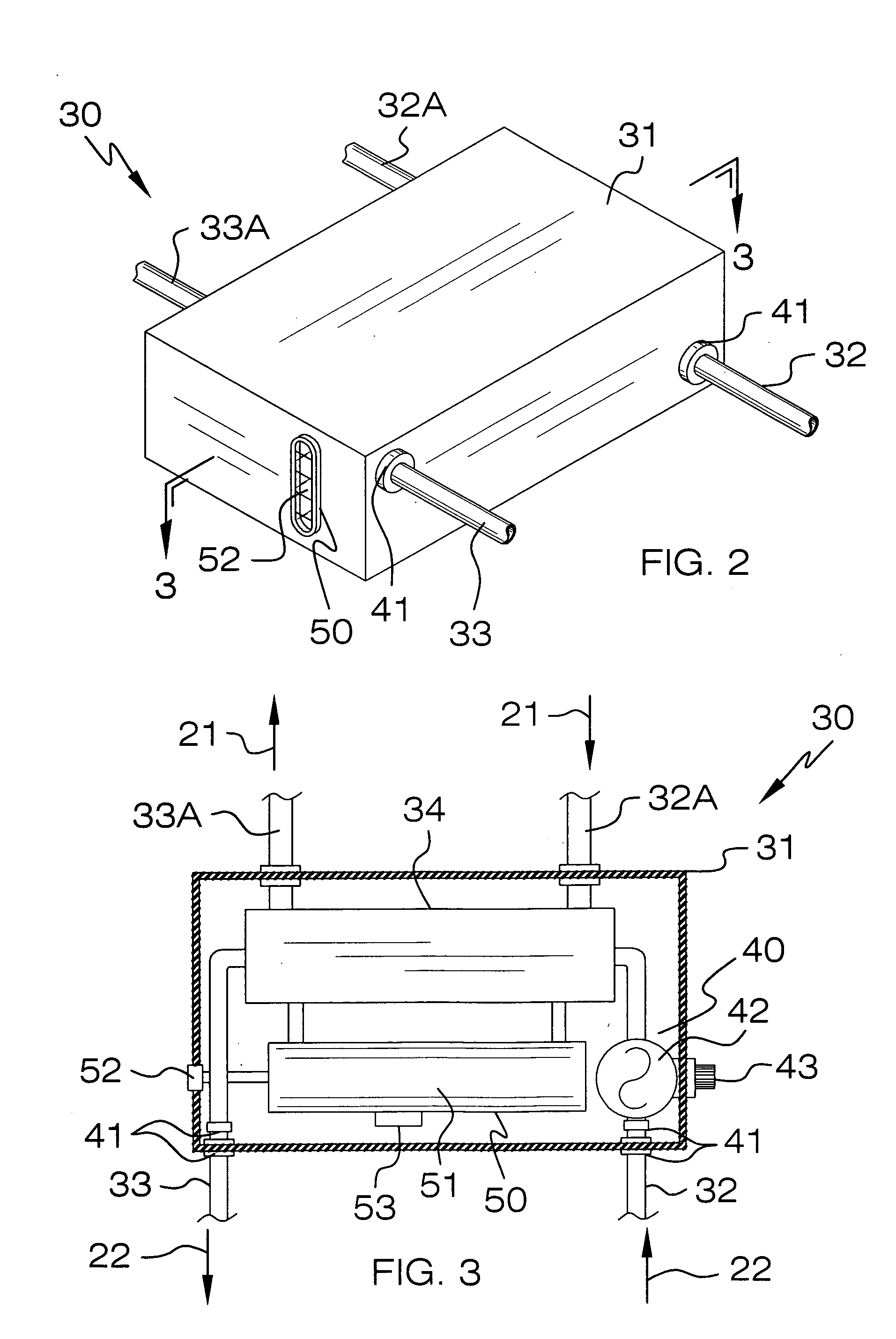
  • Coolant regulating system for tractor trailers

Examples


Embodiment Construction

[0023]The present invention will now be described more fully hereinafter with reference to the accompanying drawings, in which a preferred embodiment of the invention is shown. This invention may, however, be embodied in many different forms and should not be construed as limited to the embodiment set forth herein. Rather, this embodiment is provided so that this application will be thorough and complete, and will fully convey the true scope of the invention to those skilled in the art. Like numbers refer to like elements throughout the figures.

[0024]The system of this invention is referred to generally in FIGS. 1–4 by the reference numeral 10 and is intended to provide a coolant regulating system for tractor trailers. It should be understood that the system 10 may be used to regulate temperature in many different types of settings and should not be limited in use to only tractor trailers.

[0025]Referring initially to FIG. 4, the system 10 includes a control switch 20 mounted to an i...


PUM


Abstract

A system includes a control switch mounted in a tractor cabin and is electrically mated to a power source of the tractor. A first coolant is housed within the tractor's engine and a second coolant is housed within a trailer's heating system. The first and second coolants have unique boiling and freezing temperatures respectively. A mechanism is included for simultaneously transferring heat from the first coolant to the second coolant while maintaining the coolants isolated. The first and second coolants have first temperatures entering and second temperatures exiting the heat transferring mechanism, respectively. The first coolant second temperature is lower than the second coolant second temperature. Mechanism are included for controlling an input flow rate of the second coolant upstream from the heat transfer mechanism and for replenishing the second coolant as heat is transferred between the first and second coolants.

Description

CROSS REFERENCE TO RELATED APPLICATIONS[0001]Not Applicable.STATEMENT REGARDING FEDERALLY SPONSORED RESEARCH OR DEVELOPMENT[0002]Not Applicable.REFERENCE TO A MICROFICHE APPENDIX[0003]Not Applicable.BACKGROUND OF THE INVENTION[0004]1. Technical Field[0005]This invention relates to coolant regulating systems and, more particularly, to a coolant regulating system for tractor engines and associated trailer heating systems.[0006]2. Prior Art[0007]Many tractor trailers pull temperature controlled trailer units commonly known as tank trailers which carry temperature sensitive goods. The sensitive tank trailer must continuously be kept at hot operating temperature in order to prevent goods from being damaged. Conventionally, the truck's cooling system and the tank trailer's heating system are integrated to be heated by the same cooling unit with antifreeze.[0008]This practice, however, is not desirable, since cross-contamination occurs between antifreeze entering from the trailer and antif...

Claims


Application Information

Patent Timeline
Patent Type & Authority Patents(United States)
IPC IPC(8): F01P9/00
CPCF01P3/20F01P2060/08F01P2050/06F01P2007/146
Inventor CRAIG, STEPHEN H.
Owner CRAIG STEPHEN H
Features
  • R&D
  • Intellectual Property
  • Life Sciences
  • Materials
  • Tech Scout
  • Unparalleled Data Quality
  • Higher Quality Content
  • 60% Fewer Hallucinations
Learn More