Electromagnetic actuator for controlling a valve of an internal combustion engine and internal combustion engine equipped with such an actuator

a technology of electric actuator and internal combustion engine, which is applied in the direction of non-mechanical valves, magnetic bodies, instruments, etc., can solve the problems of high current and hence a higher consumption of actuators, and achieve the effects of reducing the force of attraction of plates, increasing the ease of assembly of actuators, and good mechanical rigidity

Active Publication Date: 2007-01-02
PEZHO SITROEN AUTOMOBILS SA +1
View PDF8 Cites 15 Cited by
  • Summary
  • Abstract
  • Description
  • Claims
  • Application Information

AI Technical Summary

Benefits of technology

[0014]In such an actuator, the magnetic field of the electromagnet circulates via the connecting part of the actuator when the plate is attracted or maintained by the actuator such that the efficiency of the action of the electromagnet on the plate is not diminished by the presence of a magnet.
[0015]Consequently, the magnetic field of the electromagnet passes only partially through the magnet that is associated with it during this operation of the actuator (attraction and maintenance of the plate) such that there is no risk of the magnet being demagnetized.
[0016]Also, if a defluxing field intended to compensate the field of the magnet is used by the actuator during the separation from the plate, this field passes through the air gap in the direction opposite that generated by the magnet and thus reduces the force of attraction of the plate.
[0017]In addition, an actuator according to the present invention has a fixed magnetic circuit at the level of the electromagnet, which is formed by a single piece, which leads to good mechanical rigidity and increased ease of assembly of the actuator.

Problems solved by technology

As a consequence of this, a higher current and hence a higher consumption is necessary for the actuator to control the valve.

Method used


Image

  • Electromagnetic actuator for controlling a valve of an internal combustion engine and internal combustion engine equipped with such an actuator
  • Electromagnetic actuator for controlling a valve of an internal combustion engine and internal combustion engine equipped with such an actuator
  • Electromagnetic actuator for controlling a valve of an internal combustion engine and internal combustion engine equipped with such an actuator

Examples


Embodiment Construction

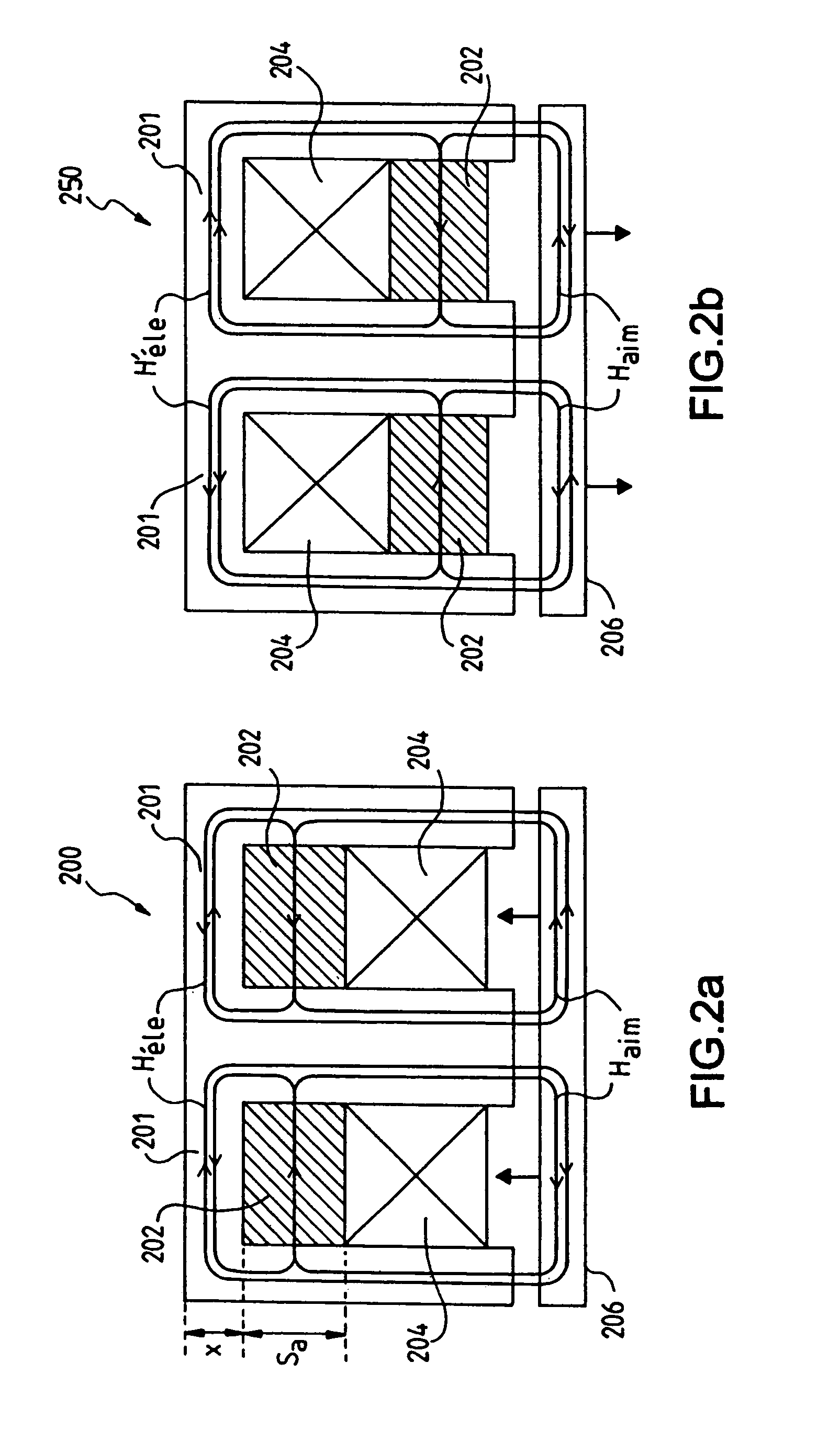
[0035]FIG. 2a shows an E-shaped actuator 200 equipped with magnets 202 generating a magnetic field Hmag, and an electromagnet 204 generating a magnetic field Hele for attracting and possibly maintaining the plate 206 against the actuator 200.

[0036]According to the present invention, the actuator comprises an connecting part 201 forming a magnetic circuit for a part of the field Hmag generated by a magnet 202, this connecting part being magnetically saturated by this partial field of the magnet when the actuator is not generating any flux.

[0037]However, when the plate 206 is attracted by the actuator 200, the field Hele generated by the electromagnet 200 has a direction opposite the sense of the field of the magnet in this connecting part.

[0038]In other words, the action of the fields of the magnets 202 and of the electromagnet 204 is combined at the level of the plate 206, ensuring an intense action on the latter, whereas these fields have opposite senses at the level of the connect...


PUM

PropertyMeasurementUnit
thicknessesaaaaaaaaaa
heightaaaaaaaaaa

Abstract

The present invention pertains to an electromechanical actuator controlling a valve of an internal combustion engine by means of a first magnetic field, generated in a variable manner by an electromagnet, and a second magnetic field, generated by at least one magnet associated with the electromagnet. According to the present invention, the actuator is characterized in that it comprises at least one connecting part forming a magnetic circuit facilitating the passage of the flux generated by the electromagnet for part of the field generated by the magnet, the connecting part being magnetically saturated by the partial field of the magnet.

Description

[0001]This application claims priority under 35 U.S.C. §119(a) to French Patent Application No. 04 50092, filed on Jan. 15, 2004.FIELD OF THE INVENTION[0002]The present invention pertains to an electromagnetic actuator for controlling a valve for an internal combustion engine and to an internal combustion engine equipped with such an actuator.BACKGROUND[0003]An electromagnetic actuator 100 (FIG. 1) for a valve 110 comprises mechanical means, such as springs 102 and 104, and electromagnetic means, such as electromagnets 106 and 108, for controlling the position of the valve 110 by means of electric signals.[0004]The stem of the valve 110 is applied for this purpose against the rod 112 of a magnetic plate 114 located between the two electromagnets 106 and 108.[0005]When a current is flowing in the coil 109 of the electromagnet 108, the latter is activated and generates a magnetic field attracting the plate 114, which will come into contact with it.[0006]The simultaneous displacement o...

Claims


Application Information

Patent Timeline
Patent Type & Authority Patents(United States)
IPC IPC(8): F01L9/04F01L9/20G01R31/00H01F7/122H01F7/16
CPCF01L9/04H01F7/122F01L2009/0436H01F7/1646F01L2009/0448F01L2009/2136F01L2009/2148F01L9/20
Inventor LECRIVAIN, MICHELGABSI, MOHAMEDBEN AHMED, HAMIDSEDDA, EMMANUELFAGEON, CHRISTOPHE
Owner PEZHO SITROEN AUTOMOBILS SA
Why Eureka
Try Eureka