Hybrid microprocessor controlled ventilator unit

a microprocessor and ventilator technology, applied in the field of hybrid microprocessor controlled ventilator units, can solve the problems of limited features and ventilation modes, lack of many advanced features found in more sophisticated ventilators, and devices with limited utility, so as to achieve the effect of reducing the work of breathing

Inactive Publication Date: 2007-01-02
UNIV OF FLORIDA RES FOUNDATION INC
View PDF55 Cites 35 Cited by
  • Summary
  • Abstract
  • Description
  • Claims
  • Application Information

AI Technical Summary

Benefits of technology

[0019]It is an object of the present invention to provide an inexpensive full featured ventilator unit having a “basic” and “advanced” mode that, in the basic mode, can be operated by health care providers having limited respiratory training and that, in the advanced mode, can be operated by skilled healthcare providers as a full featured ICU ventilator.
[0023]It is a further object of the present invention to provide a ventilator having a BUV lockout system. The lockout system prevents the BUV from operating, using previously set ventilation parameters, during initial power-up of the ventilator unit.
[0024]It is a further object of the present invention to provide a ventilator having a mechanism for adaptively setting the rate of airway pressure rise during pressure support ventilation (PSV). This mechanism will allow the rate of rise, that best minimizes work of breathing for the patient, to be automatically set shortly after the PSV mode is activated.
[0027]It is a further object to the present invention to provide a ventilator having a mechanism for automatically setting ventilation parameter limits based on body length of the patient and which thereby prevents unskilled users from setting ventilation parameters which may be dangerous to the patient.

Problems solved by technology

The ventilator / resuscitator is designed for use by personnel with limited respiratory training and thus has limited features and ventilation modes.
In particular, the minimally featured ventilators can maintain ventilation of seriously ill patients, however, they lack many of the advanced features found on the more sophisticated ventilators.
These devices have limited utility in that they are suited only to short term ventilation such as would be necessary during transport situations.
In contrast, the more sophisticated ventilators are generally more costly, larger and require more training to operate than the minimally featured ventilators.
As a result the more sophisticated ventilators are impractical for use in many environments such as aero-medical transport, in emergency departments, during intra-hospital transport and in hospitals of developing or third world countries.
In the prior devices which are microprocessor controlled or utilize electrically driven gas supplies, an electrical failure can result in an inoperative ventilator.
Alternatively, the prior devices, which are pneumatically driven and controlled, lack many of the advanced safeties and features available through the use of modern microprocessor technology.
In emergency situations the difficulty in accurately determining a patient's weight as well as errors in inputting the parameters can result in improper, even dangerous, ventilator settings.
The prior art devices do not provide for safety mechanisms to prevent such occurrences.

Method used


Image

  • Hybrid microprocessor controlled ventilator unit
  • Hybrid microprocessor controlled ventilator unit
  • Hybrid microprocessor controlled ventilator unit

Examples


Embodiment Construction

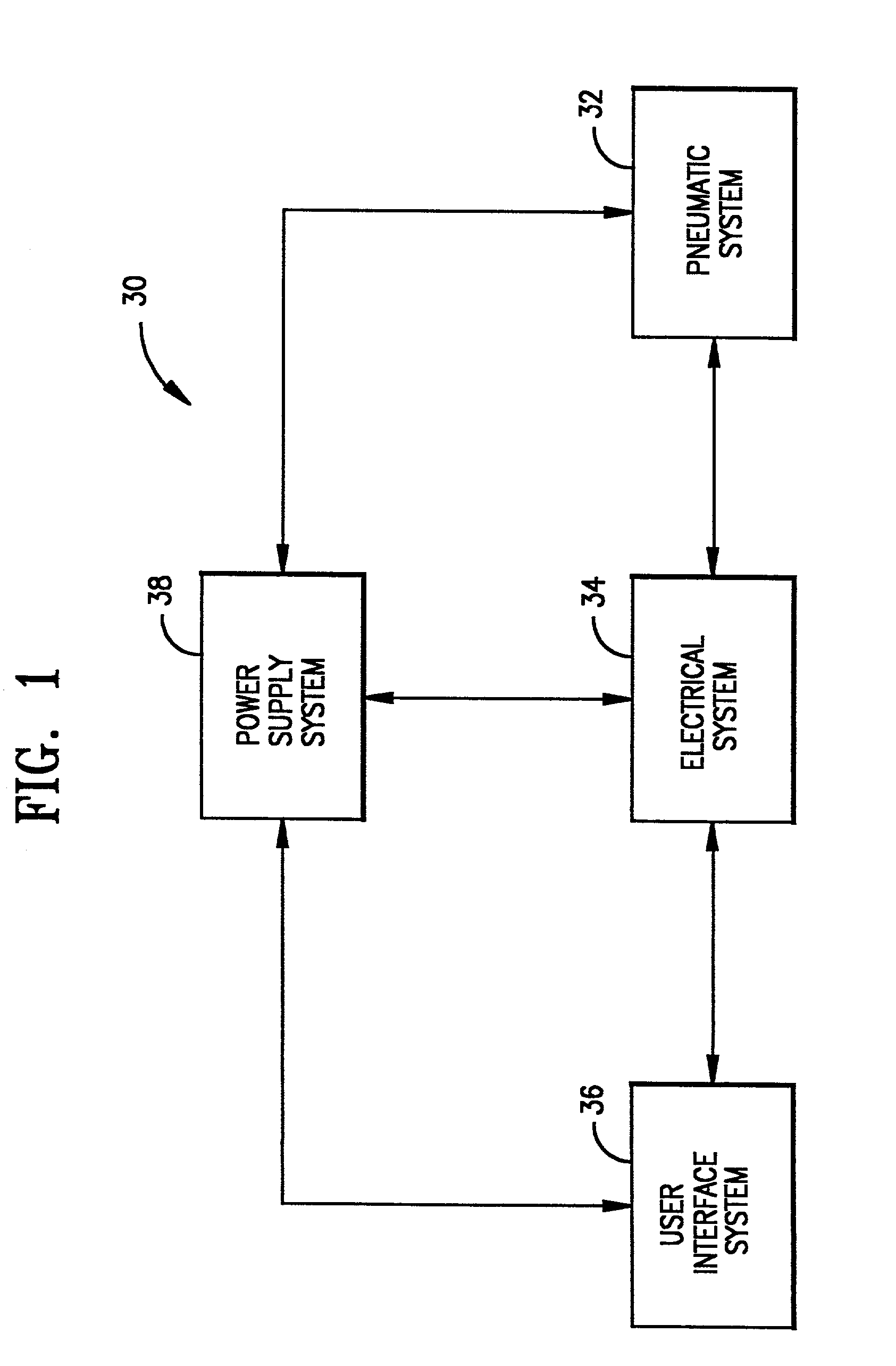
[0051]Referring now to the figures, wherein like numerals indicate like elements, in FIG. 1 there is shown a block diagram illustration of a ventilator, generally designated by reference number 30, in accordance with a preferred embodiment of the present invention. The ventilator includes a pneumatic system 32, an electrical system 34, a user interface system 36 and a power supply system 38. Each of these systems will be set forth and described below.

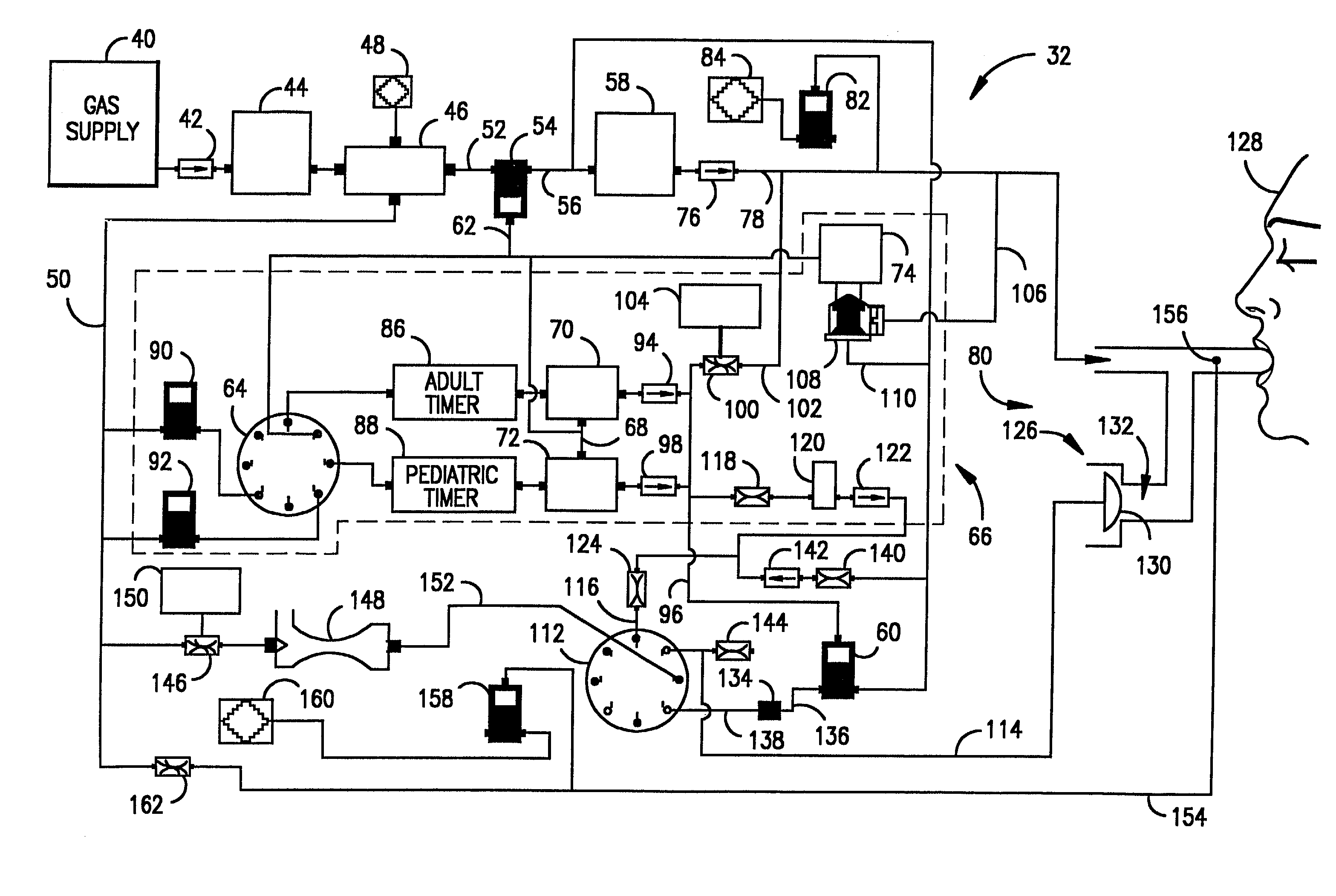
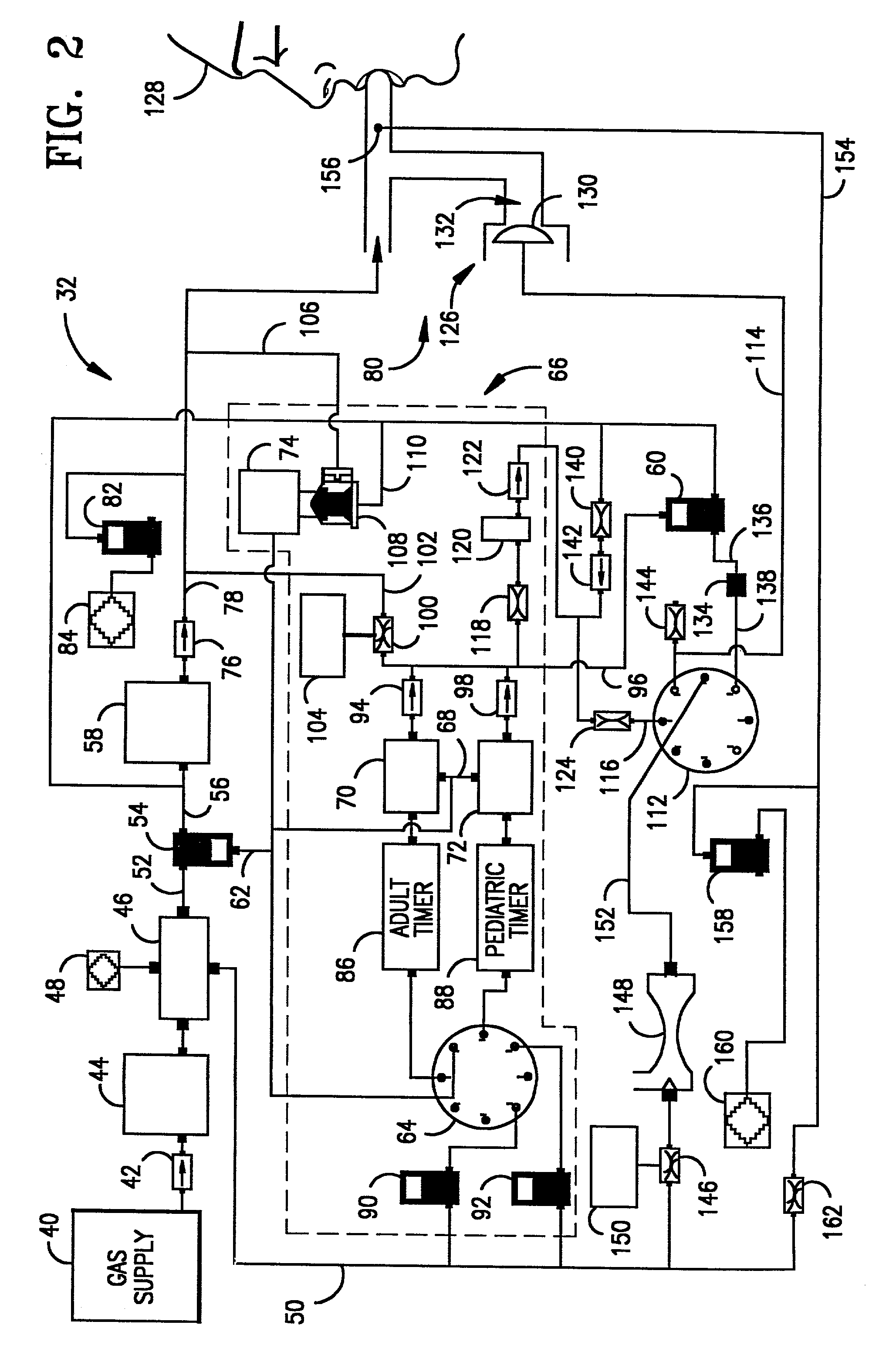
[0052]In FIG. 2 there is shown the pneumatic system 32 of the ventilator of FIG. 1. The pneumatic system 32 includes a primary ventilator sub-system and a back-up ventilator sub-system. Each of these sub-systems will be described below.

[0053]In operation, gas is supplied to the pneumatic system 32, from a gas supply 40, at the input of a one way check valve 42. The gas may be air, pure oxygen or a mixture thereof. The gas supply 40 provides the gas at a pressure at least sufficient to force the gas through the system, to operate the pne...


PUM


Abstract

A method and apparatus for operating a ventilator in a primary electronic mode or in a back-up pneumatic mode during primary electronic mode failure. A method and apparatus for operating a ventilator in an advanced mode, having a number of ventilatory modes, or in a basic mode, having a limited number of ventilatory modes is also disclosed.

Description

[0001]This is a divisional application based upon U.S. patent application Ser. No. 09 / 457,709, filed on Dec. 10, 1999, now U.S. Pat. No. 6,976,487 which is a continuation of U.S. patent application Ser. No. 08 / 516,478, filed Aug. 17, 1995 now U.S. Pat. No. 6,000,396, issued on Dec. 14, 1999, both of which are hereby incorporated in their entireties by reference.FIELD OF THE INVENTION[0002]The present invention relates to a ventilator unit. More particularly, the present invention relates to a hybrid microprocessor controlled ventilator unit. The ventilator of the present invention may be operated either in a basic mode, as a minimally featured transport ventilator unit, or in an advanced mode as a full featured ventilator for use in transport situations, in emergency situations or in ICU situations.BACKGROUND OF THE INVENTION[0003]Ventilation is the physiologic process of moving a gas into and out of the lungs and thereby delivering oxygen to organs of the body and excreting carbon ...

Claims


Application Information

Patent Timeline
Patent Type & Authority Patents(United States)
IPC IPC(8): A61M16/00A62B7/00A61M16/20
CPCA61M16/00A61M16/206A61M2016/0021A61M2205/16A61M2016/0027A61M16/0858A61M16/208A61M16/203A61M16/205A61M16/209A61M16/0051A61M16/026
Inventor MELKER, RICHARD J.BANNER, MICHAEL J.LAMPOTANG, SAMSUNBLANCH, PAUL B.EULIANO, NEIL R.CAROVANO, RONALD G.
Owner UNIV OF FLORIDA RES FOUNDATION INC
Why Eureka
Try Eureka