Installation tool for interlocking grooved flooring panels

a technology for installing tools and flooring, applied in the direction of lifting devices, manufacturing tools, metal-working machine components, etc., can solve the problems of unsuitable laminate flooring accessories, etc., and achieve the effect of quick and secure interlocking

Inactive Publication Date: 2007-01-02
JACOBS CHARLES A
View PDF11 Cites 26 Cited by
  • Summary
  • Abstract
  • Description
  • Claims
  • Application Information

AI Technical Summary

Benefits of technology

[0011]In view of the foregoing background, it is therefore an object of the present invention to provide an installation tool for interlocking grooved flooring panels. These and other objects, features, and advantages of the invention are provided by a hand-operable and portable tool for advantageously and effectively assisting an operator to quickly and securely interlock laminate strip panels together while simultaneously laying the laminate strip panels on a floor surface.

Problems solved by technology

Unfortunately, these apparatuses are not suitable in use with laminate flooring due to angle at which the separate panels must ideally be engaged to ensure a gap-free and tight fit therebetween.

Method used


Image

  • Installation tool for interlocking grooved flooring panels
  • Installation tool for interlocking grooved flooring panels
  • Installation tool for interlocking grooved flooring panels

Examples


Embodiment Construction

[0031]The present invention will now be described more fully hereinafter with reference to the accompanying drawings, in which preferred embodiments of the invention are shown. This invention may, however, be embodied in many different forms and should not be construed as limited to the embodiments set forth herein. Rather, these embodiments are provided so that this application will be thorough and complete, and will fully convey the true scope of the invention to those skilled in the art. Like numbers refer to like elements throughout the figures and prime numbers refer to alternate embodiments of such elements.

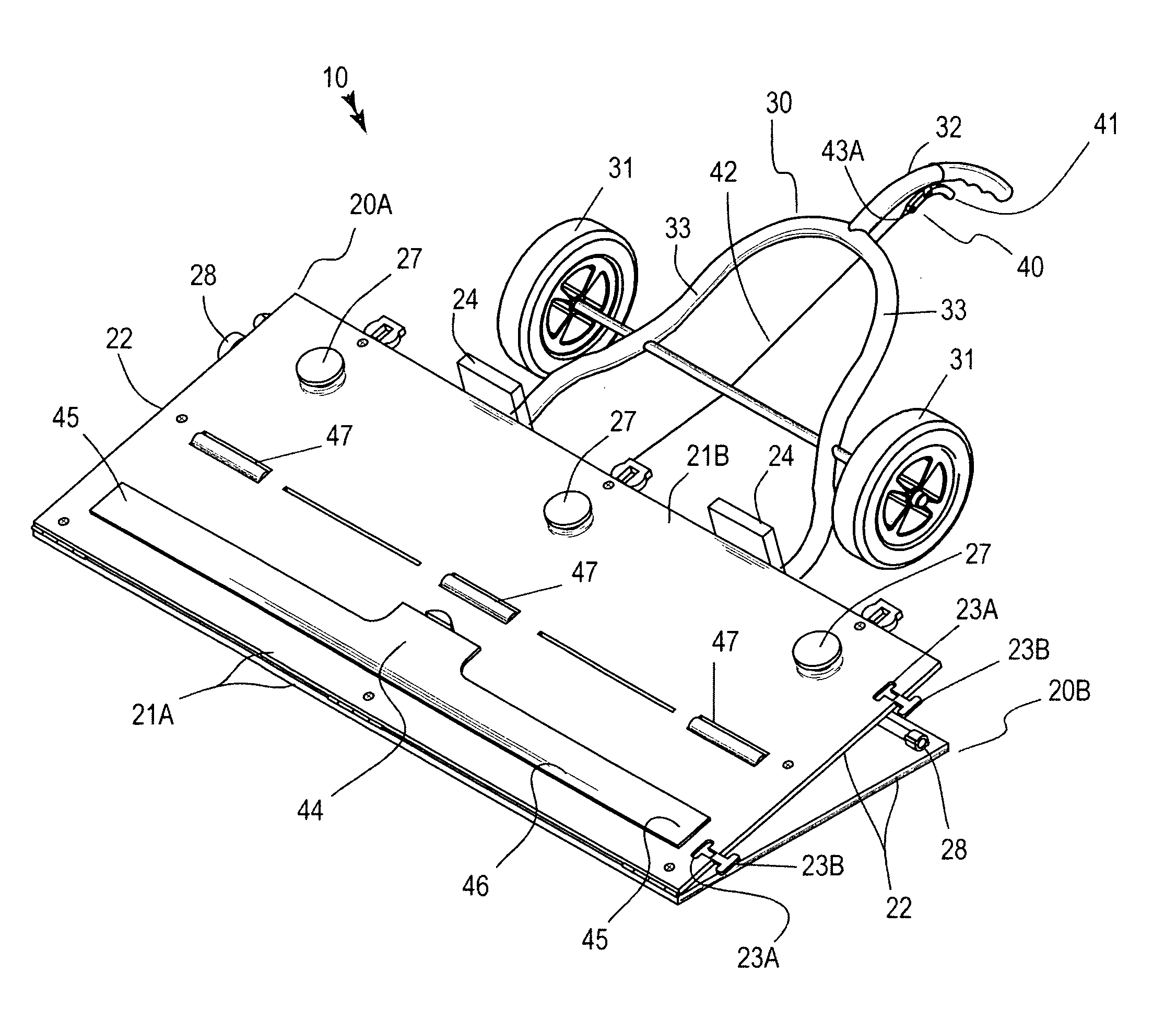
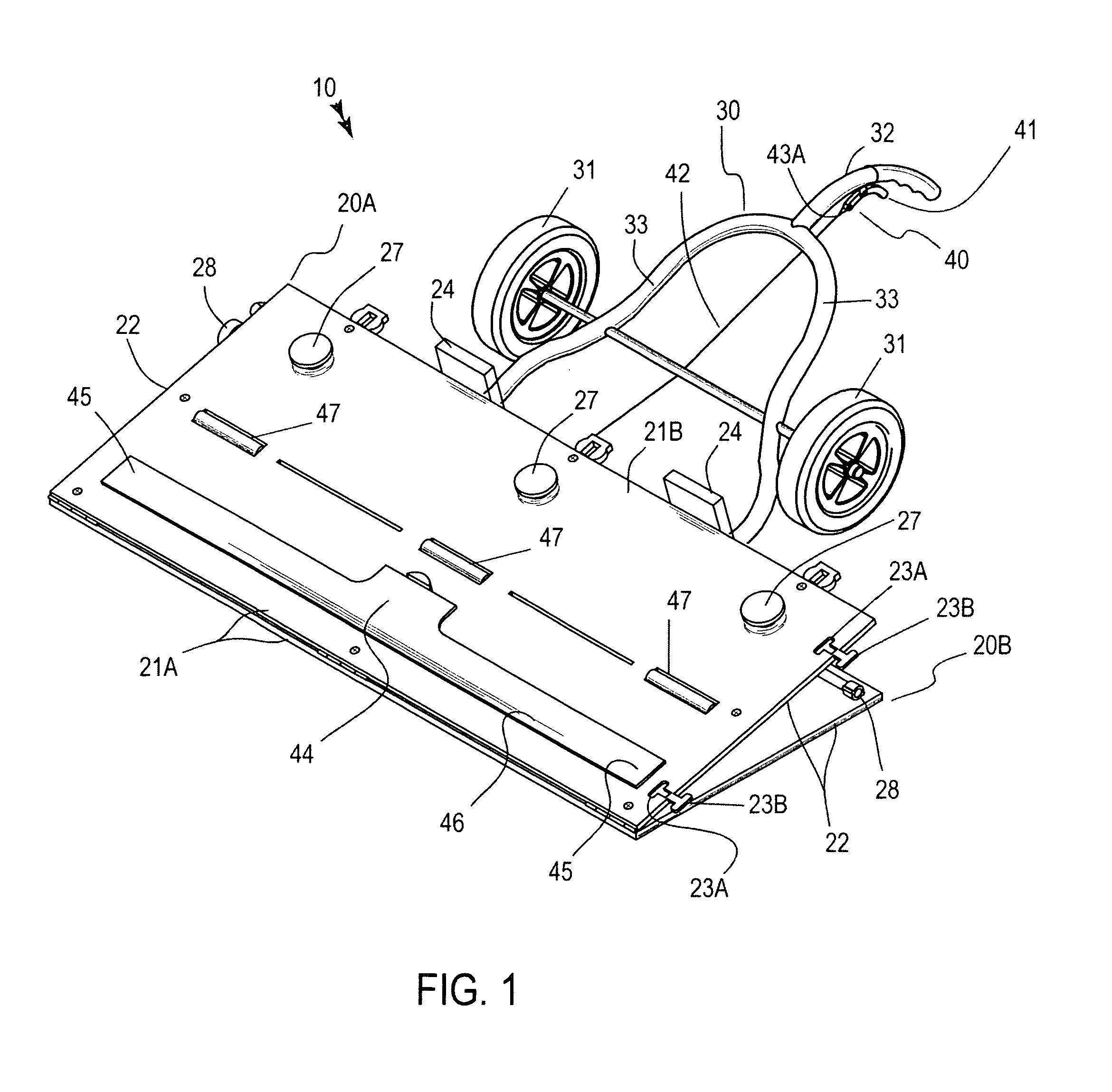
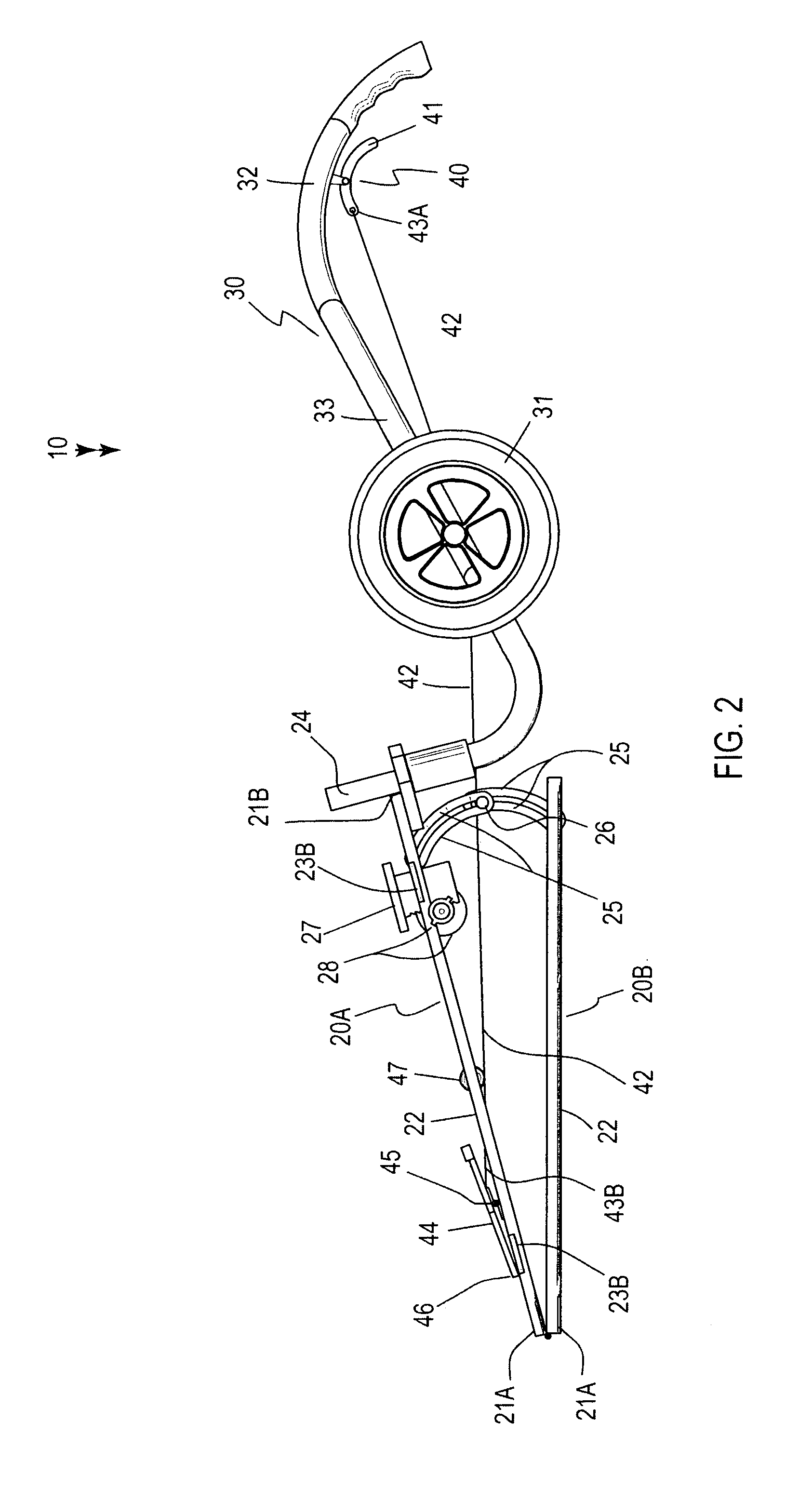
[0032]The apparatus of this invention is referred to generally in FIGS. 1–8 by the reference numeral 10 and is intended to provide an installation tool for interlocking grooved flooring panels. It should be understood that the apparatus 10 may be used to install many different types of grooved flooring panels and should not be limited in use to only laminated type flooring ...


PUM


Abstract

A tool includes pivotally conjoined top and bottom planar bodies being coupled along their distal edges and having opposed linear ends. The bottom body is statically registered while the top body is dynamically articulatable. Slotted brackets are coupled to one linear end of the bodies, and are slidably interlocked and repeatedly moveable between compressed and engaged positions. Knobs traverse through the top body and are engaged therewith. The knobs are adaptable between raised and lowered positions. A turn wheel is connected to the knobs for raising and lowering the knobs in sync. A handle assembly includes wheels that are seated proximal to the bodies. A lever protrudes proximally from the wheels. A mechanism is included for preventing laminate planks from sliding downwardly along the top body. Rotatable and equidistantly spaced rollers are axially oriented along the top body and are registered with corresponding ones of the knobs.

Description

CROSS REFERENCE TO RELATED APPLICATIONS[0001]Not Applicable.STATEMENT REGARDING FEDERALLY SPONSORED RESEARCH OR DEVELOPMENT[0002]Not Applicable.REFERENCE TO A MICROFICHE APPENDIX[0003]Not Applicable.BACKGROUND OF THE INVENTION[0004]1. Technical Field[0005]This invention relates to installation tools and, more particularly, to an installation tool for interlocking grooved flooring panels.[0006]2. Prior Art[0007]It is wide-spread, conventional practice to construct buildings of many types and sizes with board sub-floors fixed in diagonal or perpendicular traversing relation to the usual floor joists and to subsequently complete the desired finish floor by means of matched boards, generally edge tongued and grooved, laid over and secured to the sub-floor. A factor of consequence in the development of high quality finish floors is the close, intimate edge matching of adjacent boards for the elimination of open cracks and seams. The practical control of said factor is aggravated by irreg...

Claims


Application Information

Patent Timeline
Patent Type & Authority Patents(United States)
IPC IPC(8): B25B1/00
CPCE04F21/22
Inventor JACOBS, CHARLES A.
Owner JACOBS CHARLES A
Why Eureka
Try Eureka