Al technical title is built by PatSnap Al team. It summarizes the technical point description of the patent document.
a structure system and hand-made technology, applied in the direction of building roofs, roof drainage, building repairs, etc., can solve the problems of increasing the cost of construction, requiring significant physical effort, time-consuming and significant expense, and adding to the cost, complexity, and effor
Active Publication Date: 2012-12-06
RUTLEDGE RICHARD BRUCE
View PDF33 Cites 25 Cited by
Summary
Abstract
Description
Claims
Application Information
AI Technical Summary
This helps you quickly interpret patents by identifying the three key elements:
Problems solved by technology
Method used
Benefits of technology
[0027]Inherent in the modular nature of the component design is the ability to create finished structures of custom or variable horizontal surface configurations, thereby allowing structures to be installed around, or
Problems solved by technology
All of these require significant physical effort, are time-consuming, and of significant expense.
Adding railing/fencing to the structure, or wall-height partitions for privacy and/or security, adds to the effort, complexity, and expense.
Unfortunately, the Decking System of Dantzer still makes use of nails, screws, bolts, etc., for connecting the components.
In addition, not all components are precut or preassembled, which means that some cutting of components and/or materials would be necessary.
The Dantzer design does not allow the installation of railings or pa
Method used
Image
Click on the blue label to locate the original text in one second.
Reading with bidirectional positioning of images and text.
Examples
Embodiment Construction
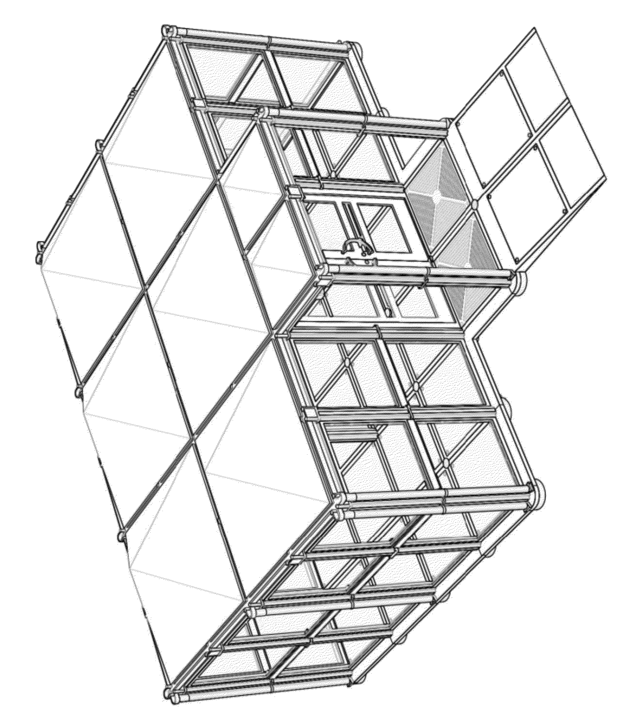
[0063]FIG. 1 is a front perspective view of an example un-roofed structure being assembled. It illustrates one possible configuration of a structure that can be assembled using a subset of components, with some of those components indicated in their relative positions for installation, and some in their installed positions.
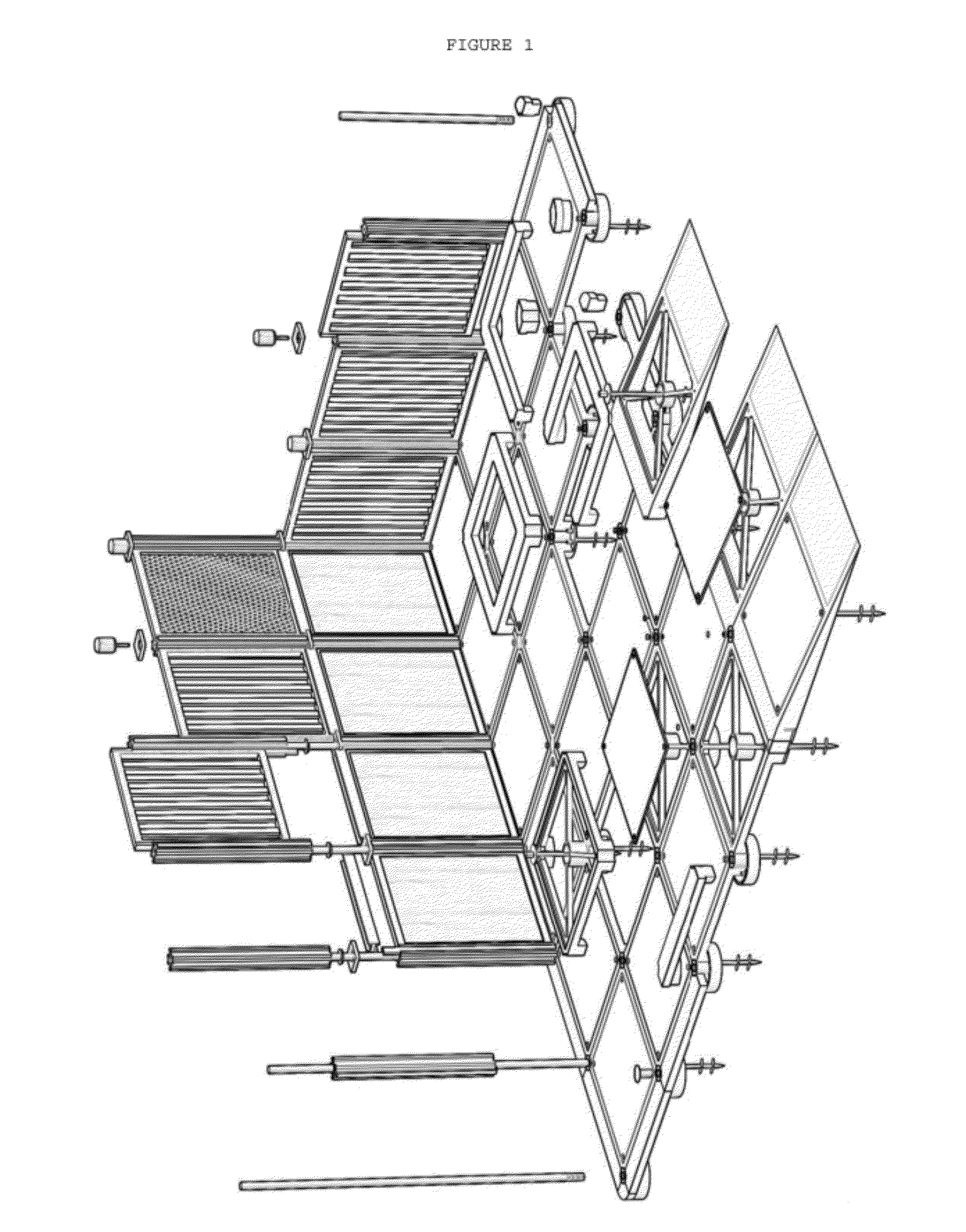
[0064]FIG. 2 is a front perspective view of a non-roofing subset of components. Combinations of these components, in varying numbers depending on the size and configuration of the desired structure, allow the assembly of unroofed structures of any desired or required size or configuration.
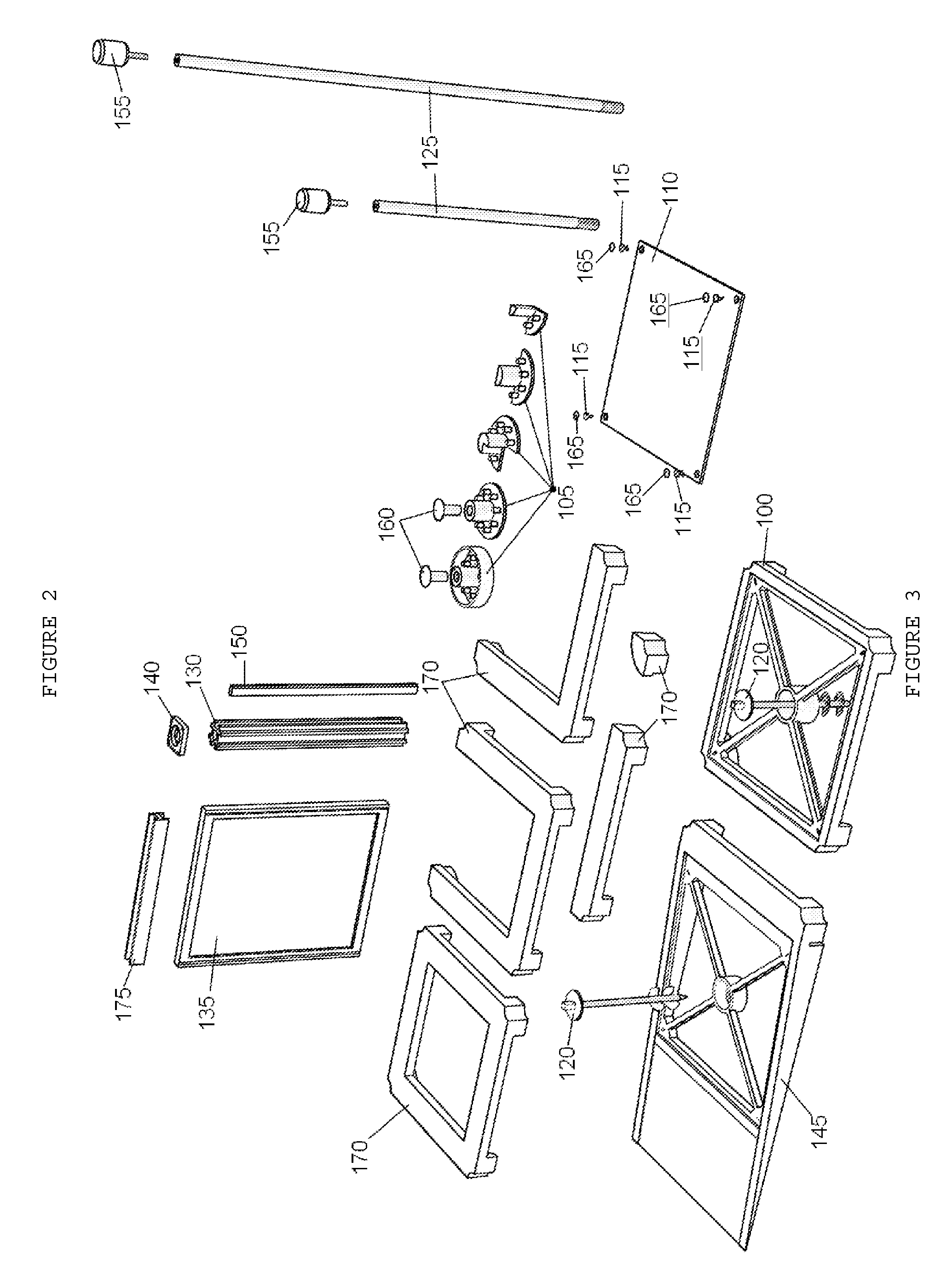
[0065]FIG. 3 is a front perspective view of a full set of Floor Panel Frame Connector 105 components. The four configurations at the top of the figure are identified as “Basic” connectors. Each is configured as one or more “quadrants” of a full circle; the “outside” corner configuration is one quadrant, the “side” is two (2) adjacent “quadrants”, the “inside” corner is three (3) ...
PUM
Abstract
A system of prefabricated modular components, designed to fit and connect together using no tools other than human hands, allowing persons with little or no construction experience to assemble floored/partitioned/roofed structures of variable shape and surface area. Flooring panels are inserted and secured into flooring frames that have been inserted and secured into frame connectors. Flooring frames may be anchored into an outdoor installation surface for long term use. Certain configurations of the frame connector allow for the installation of variable height partition supports, as well as partition panels. A special configuration of the flooring frame allows for wheeled implement/conveyance access to the floored surface from the surrounding surface. Open, unfloored areas may be created within the periphery of a structure. Roof Panels are installed onto and supported by Roof Brackets, Roof Beams and Integrated Gutter Sections. Precipitation is conveyed to Downspout Pipes and Fittings via Downspouts.
Description
RELATED APPLICATIONS[0001]The present application is incorporated by reference to provisional application 61351911, confirmation number 9568, Docket Number HSS2009.FIELD OF THE INVENTION[0002]The present invention relates to the assembly of temporary or permanent structures (borders, enclosures, decking, walkways, platforms, sheds, cabins, etc.), indoors or outdoors, and more particularly, to assembling temporary or permanent indoor or outdoor structures (borders, enclosures, decking, walkways, platforms, sheds, cabins, etc.) without requiring the use of any tools other than human hands for assembly.BACKGROUND OF THE INVENTION[0003]The building of structures for recreational or utility purposes (decks, walkways, platforms, etc.) traditionally requires the person building the structure to have at least moderate carpentry and construction skills. In addition, tools and materials such as hammers, nails, screws and screwdrivers, saws, etc., are required. Depending on the size and scale ...
Claims
Application Information
Patent Timeline
Application Date:The date an application was filed.
Publication Date:The date a patent or application was officially published.
First Publication Date:The earliest publication date of a patent with the same application number.
Issue Date:Publication date of the patent grant document.
PCT Entry Date:The Entry date of PCT National Phase.
Estimated Expiry Date:The statutory expiry date of a patent right according to the Patent Law, and it is the longest term of protection that the patent right can achieve without the termination of the patent right due to other reasons(Term extension factor has been taken into account ).
Invalid Date:Actual expiry date is based on effective date or publication date of legal transaction data of invalid patent.