Concrete finishing tool with handle-mounted vibrating arrangement

Inactive Publication Date: 2007-01-02
ROZINSKI RICHARD M
View PDF17 Cites 7 Cited by
  • Summary
  • Abstract
  • Description
  • Claims
  • Application Information

AI Technical Summary

Benefits of technology

[0008]It is a general object of the present invention to provide an improved tool fo

Problems solved by technology

Much effort and time is taken by laborers during the screeding or striking process to achieve an initial flatness of the poured concrete.
When bull floating is done manually, it is extremely labor intensive and much strain is felt upon the operator's body.
Other devices solely employ vibrating un

Method used


Image

  • Concrete finishing tool with handle-mounted vibrating arrangement
  • Concrete finishing tool with handle-mounted vibrating arrangement
  • Concrete finishing tool with handle-mounted vibrating arrangement

Examples


Embodiment Construction

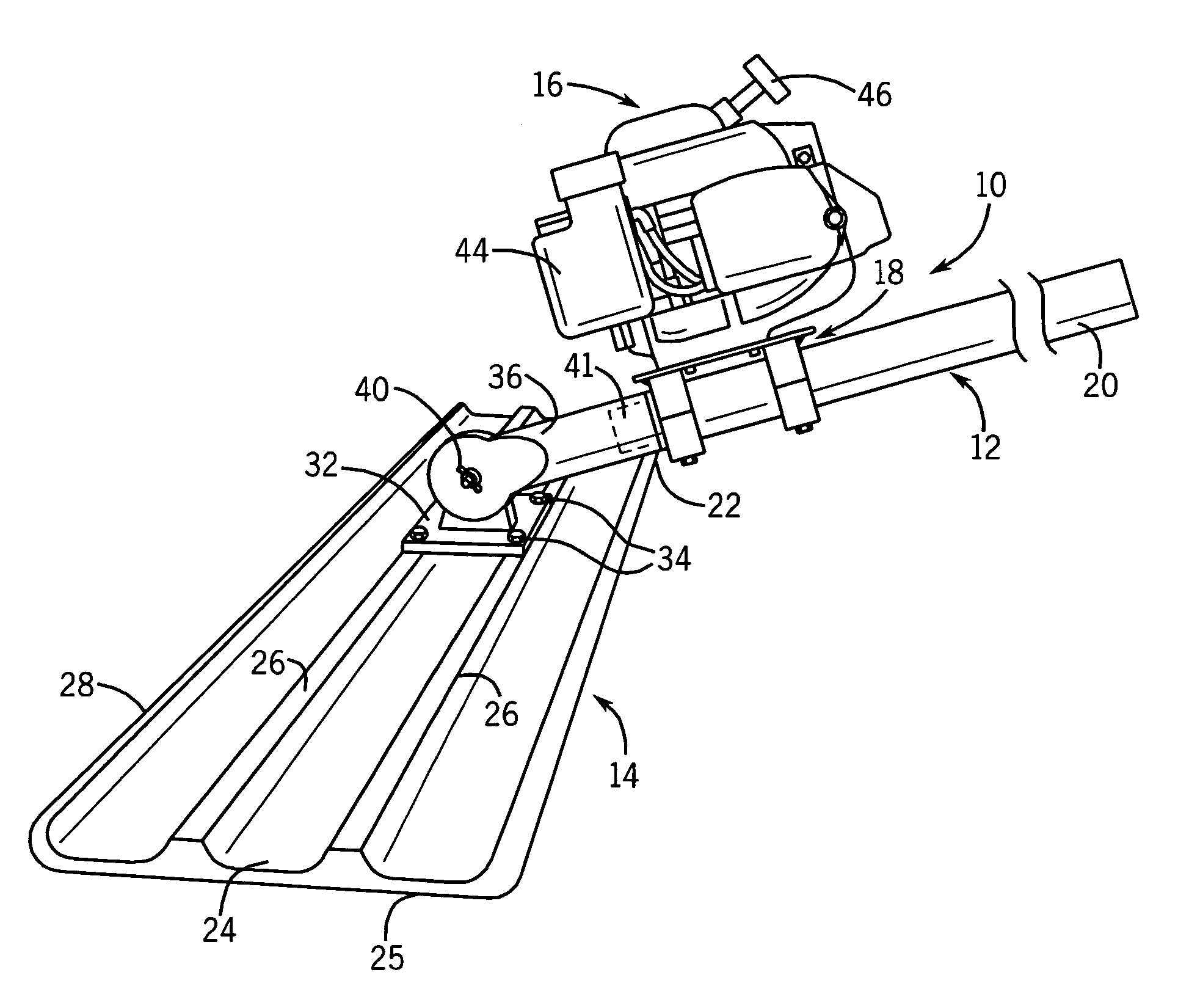
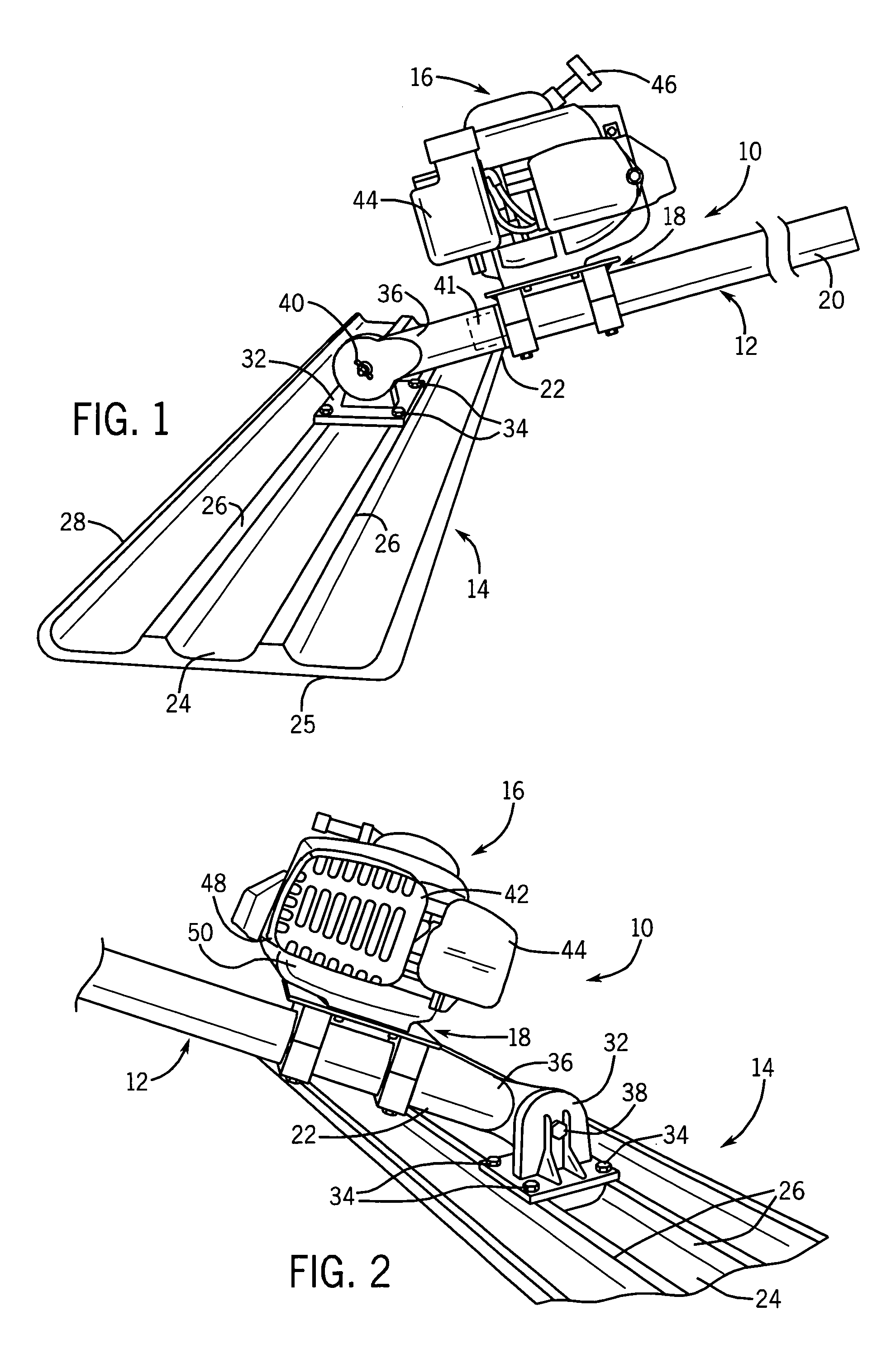
[0026]Referring now to the drawings, FIGS. 1–5 disclose a preferred embodiment of the concrete finishing tool 10 embodying the present invention.

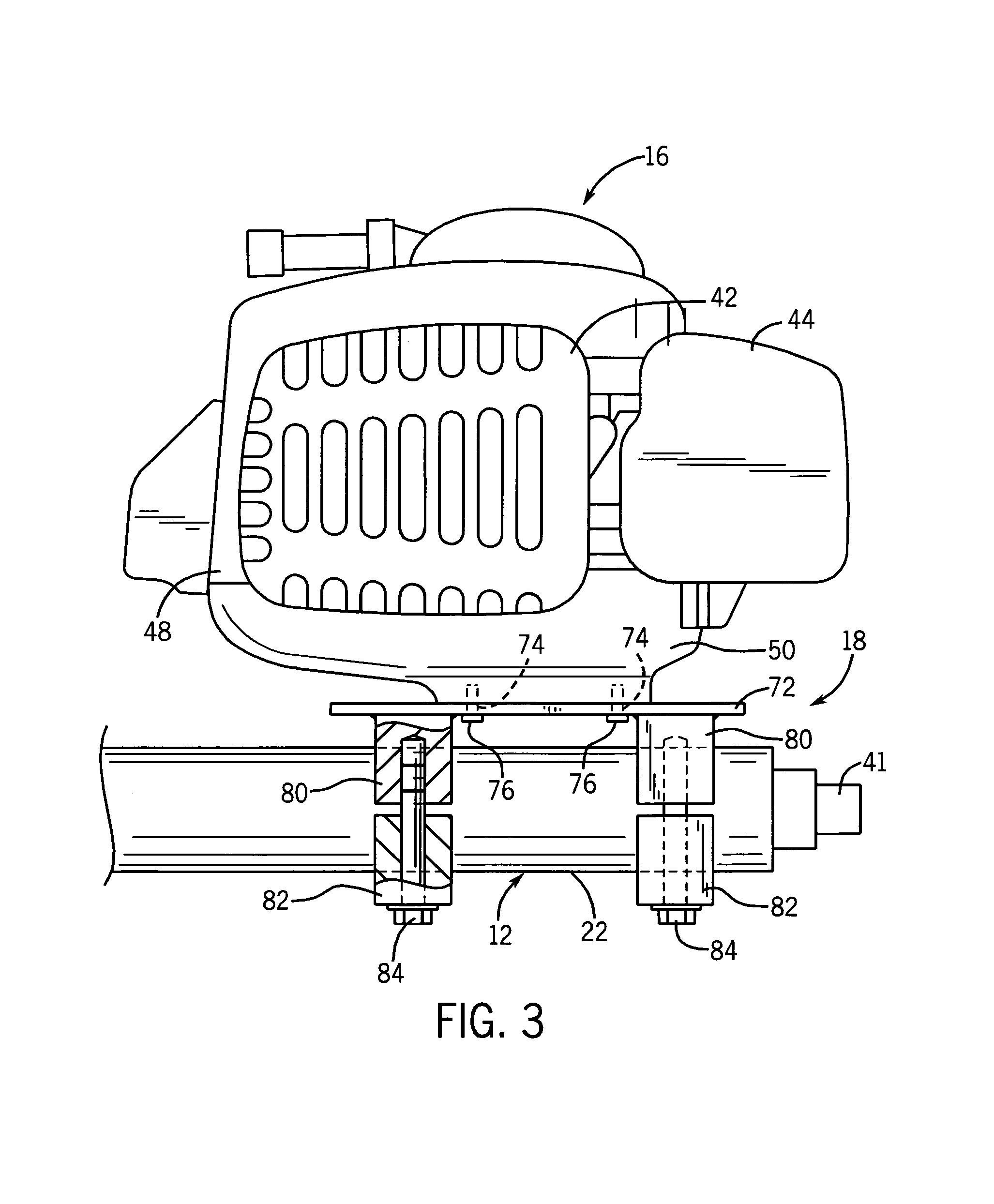
[0027]The concrete finishing tool 10 is generally comprised of an elongated handle 12, a concrete working device 14, a vibratory mechanism 16 and a clamping and vibration transmitting arrangement 18.

[0028]The elongated handle 12 has a cylindrical configuration and is typically formed by a number of aluminum or fiberglass sections which are coupled together in any suitable manner such as by cooperative screwthreaded engagement as is well known. The handle 12 is configured with a variable length having an uppermost end 20 and a lowermost end 22 to provide for the particular size of concrete slab to be finished. Handle 12 may be, for example, 20 feet long.

[0029]The concrete working device 14 preferably takes the form of a float, specifically a bull float, generally comprised of an aluminum or magnesium material. The bull float 14 is a large re...


PUM


Abstract

A vibratory concrete finishing tool includes an elongated handle formed with a cylindrical configuration having an uppermost end and a lowermost end. A concrete working device has a planar bottom surface adapted to engage a wet concrete surface, and a receiver for removably receiving the lowermost end of the handle. A clamping and vibration transmitting arrangement is coupled externally to the lowermost end of the handle. An engine-driven vibratory mechanism is fixed to the clamping and vibration transmitting arrangement so that the vibratory mechanism is held in spaced relationship with the handle. The vibratory mechanism has a spinning crankshaft assembly with an eccentric weight mounted thereon.

Description

CROSS REFERENCE TO RELATED APPLICATION[0001]This application relates to and claims priority based on U.S. Provisional Patent Application Ser. No. 60 / 686,509 filed Jun. 1, 2005.FIELD OF THE INVENTION[0002]The present invention relates generally to tools employed in the finishing of wet concrete and, more particularly, pertains to a concrete finishing tool provided with a vibrating arrangement specifically mounted and positioned on an elongated handle of the finishing tool.BACKGROUND OF THE INVENTION[0003]In the course of constructing concrete slabs and the like, liquefied concrete comprised of aggregate, cement, water and other additives is freshly poured into a form and must first be brought to a desired shape and size of the slab. This is conventionally done by screeding or striking off (i.e. spreading, distributing and leveling) the uncured concrete usually with the use of prepositioned guides or rails. Typical screeding or striking methods include manually passing the edge of a t...

Claims


Application Information

Patent Timeline
IPC IPC(8): E01C19/38
CPCE01C19/402E04F21/244E04F21/242
Inventor ROZINSKI, RICHARD M.
Owner ROZINSKI RICHARD M
Why Eureka
Try Eureka