Electrical connection box with drainage channel

a technology of electrical connection box and drainage channel, which is applied in the direction of connecting contact material, printed circuit, electrical apparatus, etc., can solve the problem of b>18/b> hardly obtained, and achieve the effect of increasing the reliability of the support of the bus bar

Active Publication Date: 2007-01-02
AUTONETWORKS TECH LTD +2
View PDF13 Cites 22 Cited by
  • Summary
  • Abstract
  • Description
  • Claims
  • Application Information

AI Technical Summary

Benefits of technology

[0009]It is an object of the present invention to provide an electrical connection box capable of reliably supporting the bus bars as well as preventing short-circuits.
[0011]Since a draining space is formed between the bus bars and the circuit casing, water drops are prevented from being accumulated on the upper surface of the circuit casing.
[0012]Accordingly, on the upper surface of the circuit casing, the adjacent bus bars are prevented from short-circuiting therebetween (short-circuit prevention).
[0015]According to the above-aspects of the invention, since each of the support plates supports each of the bus bars independently, the reliability in support of the bus bars is increased.

Problems solved by technology

However, when such space 19 is formed, satisfactory support of the bus bars 18 is hardly obtained.

Method used


Image

  • Electrical connection box with drainage channel
  • Electrical connection box with drainage channel
  • Electrical connection box with drainage channel

Examples


Embodiment Construction

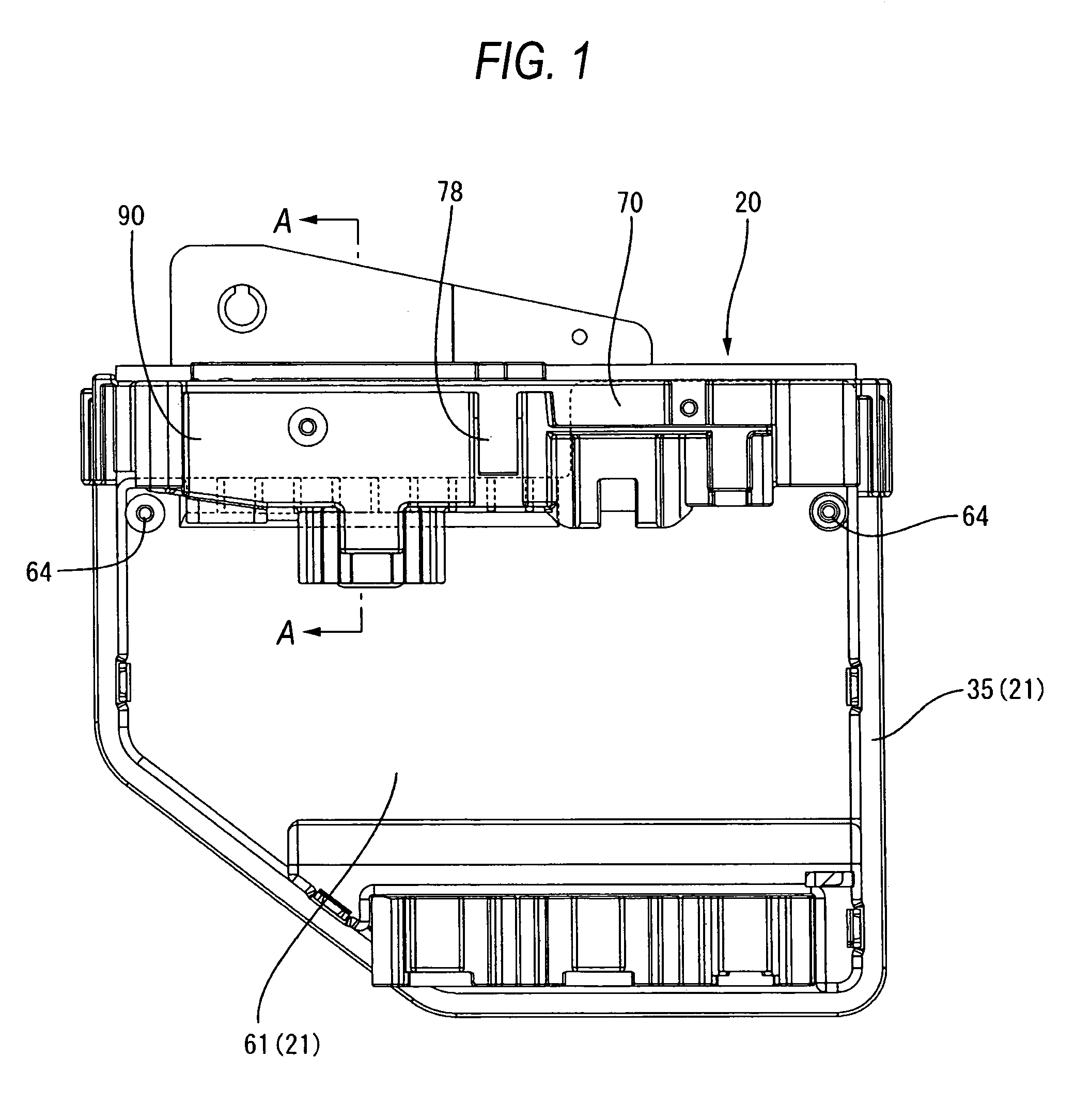
[0023]An embodiment of the present invention will be described with reference to FIG. 1 to FIG. 5.

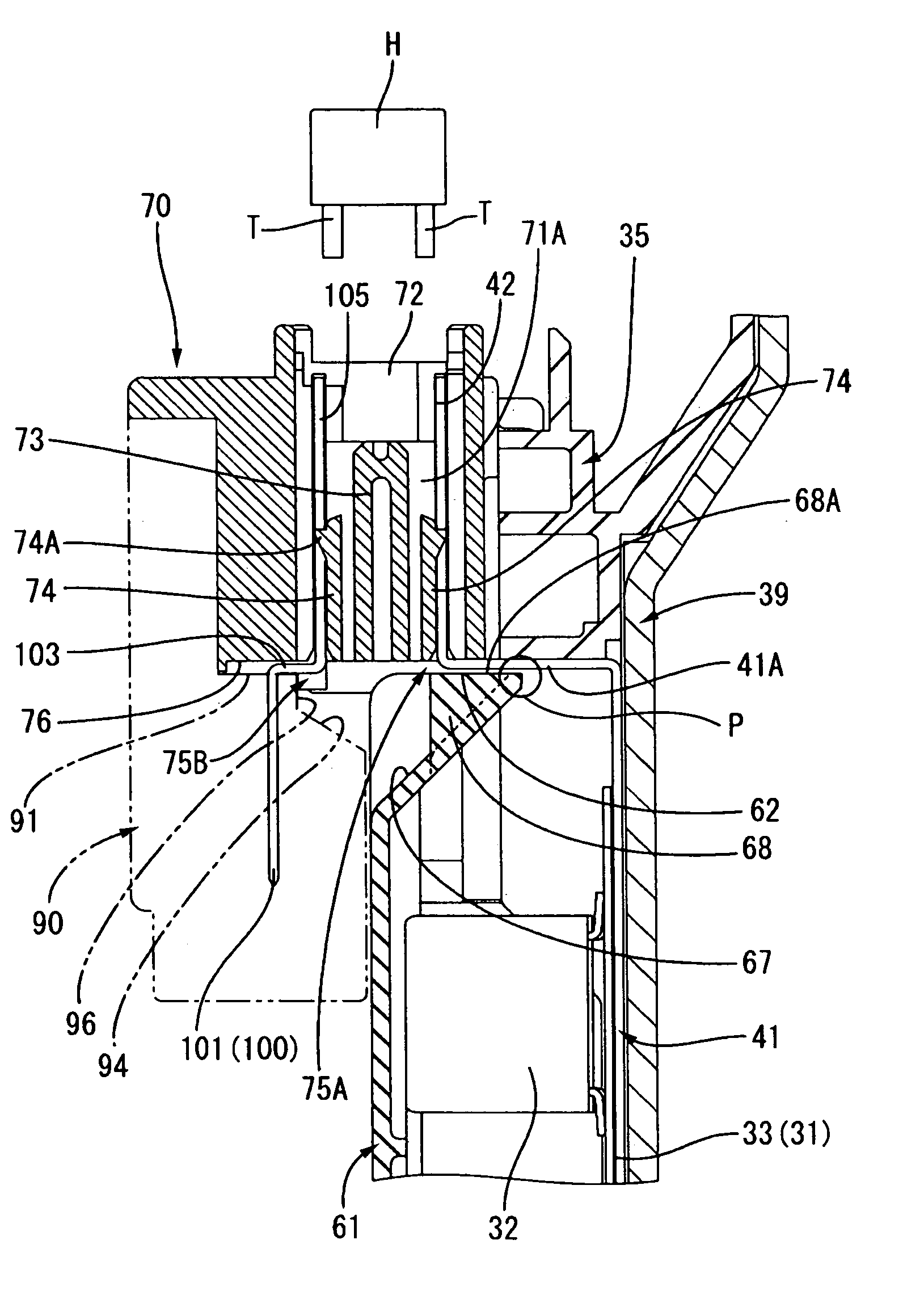
[0024]Reference numeral 20 in FIG. 1 denotes an electrical connection box used for automobiles, which is disposed being interposed between a power source such as a battery and electrical loads for distributing / supplying the power supplied from the power source to each of the electrical parts and controlling the switching of the power supply etc. The electrical connection box 20 includes mainly a casing 21 (circuit casing) for accommodating a circuit assembly unit 31, a fuse box 70 and an upper connector 90. The electrical connection box 20 is disposed, for example, in a vertical direction (the direction shown in FIG. 1) within an engine room.

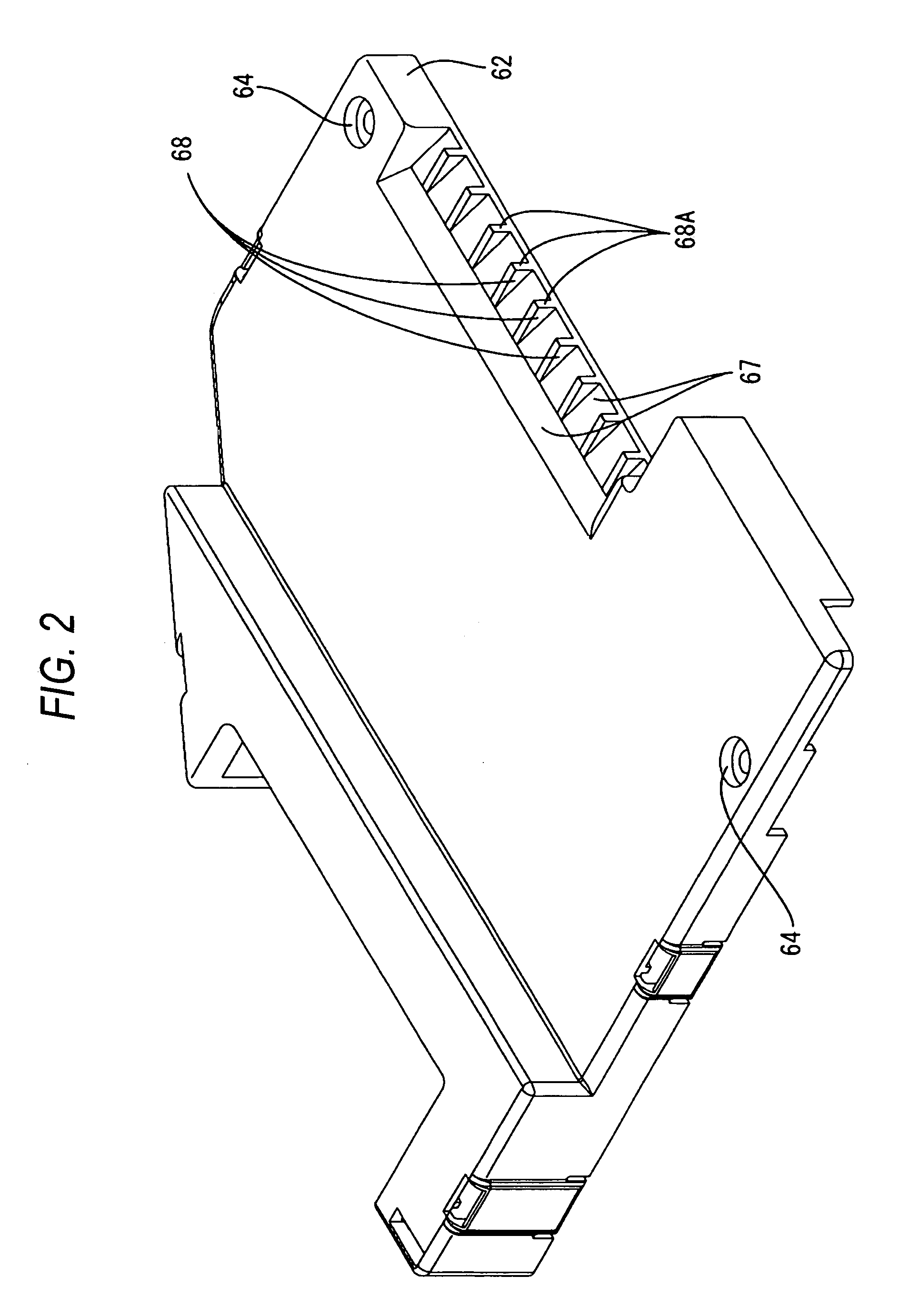
[0025]The circuit assembly unit 31 includes a circuit board 33, an electronic part 32 mounted on a circuit pattern (not shown) formed on the surface of the circuit board 33 and bus bars 41 for a board made of a metal plate, which is disposed along t...


PUM


Abstract

An electrical connection box includes a fuse box having a bottom wall, the fuse box detachably and attachably accommodating a fuse element; a circuit casing being disposed below the fuse box, the circuit casing having a supporting section on an upper surface therof; the circuit casing accommodating a circuit assembly unit; and a plurality of bus bars electrically connecting between the fuse box and the circuit assembly unit, each bus bar being pulled out from the bottom face and drawn into the circuit casing through a wiring path of bus bar along a lower surface of the bottom wall. A draining space is formed between the fuse box and the circuit casing. The supporting section supports the bus bars from a lower side of the bus bars to at least partially come into contact with the bus bar along the bottom wall.

Description

BACKGROUND OF THE INVENTION[0001]1. Field of the Invention[0002]The present invention relates to an electrical connection box.[0003]2. Description of the Related Art[0004]In JP-A-2003-348732, electrical connection boxes, which are mounted on automobiles, are occasionally disposed in an engine room or the like. Therefore, there have been taken some measures to prevent the circuit board and / or bus bars from short-circuiting due to water, which invades the engine room during washing an automobile.[0005]In the electrical connection box, on the upper face of a frame 3 for accommodating the circuit board, a mounting section 3c for connecting an external connector is integrally formed. In the mounting section 3c, a terminal receiving hole 3d is formed vertically therethrough. And in the terminal receiving hole 3d, a contact terminal (bus bars) 13 for connecting the terminals of an external connector to the circuit board is accommodated. Therefore, there is a possibility that water may inva...

Claims


Application Information

Patent Timeline
Patent Type & Authority Patents(United States)
IPC IPC(8): H01R12/00
CPCH01H85/2045H01H85/0026Y10S439/949H01R9/226H01H2085/208
Inventor YAMANE, SHIGEKI
Owner AUTONETWORKS TECH LTD
Why Eureka
Try Eureka