
DC switching device

a switching device and dc technology, applied in the direction of air-breaking switches, high-tension/heavy-dress switches, electrical apparatus, etc., can solve the problems of limited current and time, damage to the whole electrical system, and damage to the dc switching device in terms of voltage, so as to reduce current and time, increase the effect of sufficient voltage drop and quick split and cooling o

Active Publication Date: 2013-08-06
ABB (SCHWEIZ) AG
View PDF6 Cites 12 Cited by
  • Summary
  • Abstract
  • Description
  • Claims
  • Application Information

AI Technical Summary

Benefits of technology

[0010]It is a further object of the invention to provide an economical and efficient manufacturing, wherein, a three-pole AC switching device is adapted for a DC application.
[0012]As a current being disconnected, the movable contact may be separated from the stationary contact, an air gap is established and an arc is generated between the stationary and movable contacts. By providing the arc-extinguishing chamber with the permanent magnet, a magnet field is generated in the entire extinguishing area of the chamber. This magnetic field builds up a magnetic driving force that drives through the arc away from the contacts and into the splitter plates. Therefore, the arc can be quickly split and cooled off. The maximum effect of the splitter plates is therefore obtained, which increases a sufficient voltage drop and results in a quicker arc extinguishing. Consequently, an overall breaking capability is increased.
[0013]The splitter plates enclosing in the chamber may be made of non-ferromagnetic material and the chamber is provided with the permanent magnet. One advantage is that this construction prevents occurrences of short-circuits that may be generated by splitter plates made of metallic ferromagnetic material and decrease the magnetic driving force drastically. To maintain a uniform magnetic field distribution, one single piece of permanent magnet is preferred so that the arc is always driven in a favorable direction.
[0014]According to another embodiment of the invention, the permanent magnet is arranged adjacent to the splitter plate unit of the chamber to provide maximum effect.
[0017]According to a preferred embodiment of the invention, a second permanent magnet is arranged on the opposite side of the splitter plate unit. The arrangement of the first and second permanent magnets provide a symmetrical and balanced magnetic force and local effects of trapping the arc close to the wall of the chamber are avoided.
[0019]In case that an AC switching device having at least three poles for a three-phase AC application is adapted as a DC switching device in a DC application, the poles of the switching device may be connected in series to each other for simplifying the wiring of the switching. This means that the contacting unit of the mid chamber has a current direction opposite to the other contacting units. By providing the mid chamber with the splitter plates made of ferromagnetic material and each of other two with the splitter plates made of non-ferromagnetic material and a permanent magnet, a maximum flux density from the permanent magnet is obtained because all the magnetic fields will have the same directions while an opposite magnetic direction will result in a lower magnetic flux density and consequently, a lower breaking capacity.

Problems solved by technology

This arc can be very destructive and must therefore be contained, cooled and extinguished in a controlled way so that the air gap between the contacts can withstand the voltage in the circuit.
Nevertheless, this is not a case for the DC application which the current has a steady state value.
If it reignites, it can damage the whole electrical system.
However, the short distance of the air gap between the contacts results in a limited voltage drop across the air gap, the breaking capability of the DC switching device in term of voltage, current and time is therefore limited when the DC switching device is used in a relatively higher voltage and current application.

Method used


Image

  • DC switching device
  • DC switching device
  • DC switching device

Examples


Embodiment Construction

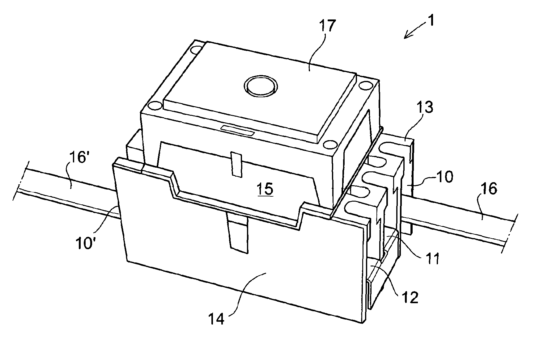
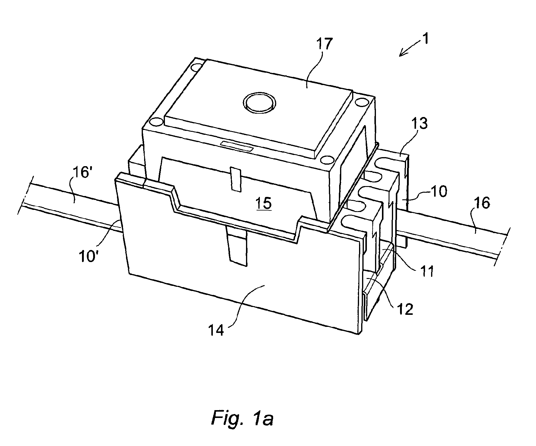
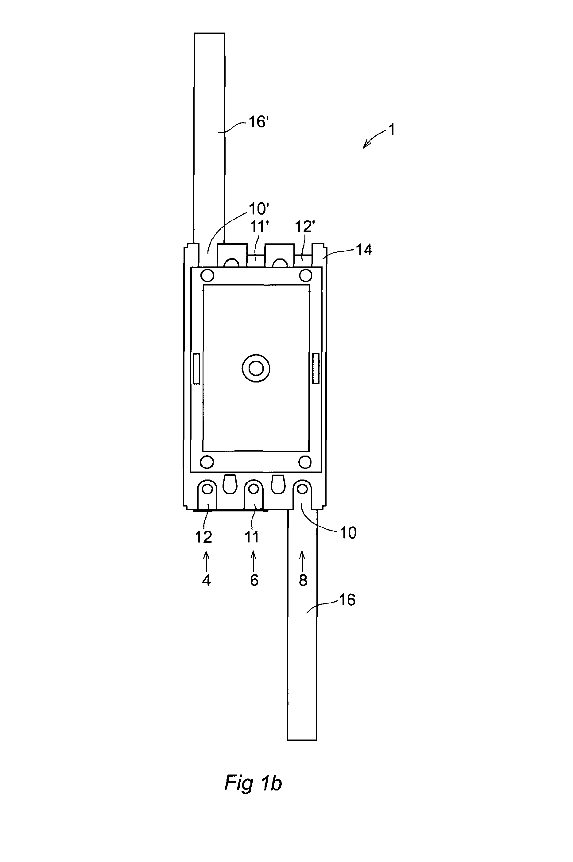
[0027]FIGS. 1a and 1b show respectively an isometric and an overhead view of a sealed electromagnetic contactor 1 comprising a housing portion 13 and a casing portion 17. The housing 13 is positioned at the bottom of the contactor in view of the FIG. 1a and includes further a frame 15 and a seat 14, while the casing portion 17 is positioned on the top part of the contactor. In this example, the contactor further includes six connectors 10, 11, 12, 10′, 11′ and 12′, wherein two connectors 10 and 10′ are arranged for connecting the contactor in an electric circuit via power terminals 16 and 16′ and, the connector 10 is connected to the terminals 16 adapted as an input terminal and the connector 10′ connected to the terminal 16′ adapted as an output terminal. While other four connectors 11, 11′, 12 and 12′ are connected in pair, meaning that the connectors 11 and 11′ are connected in series so do the connectors 12 and 12′. Therefore, all the connectors are connected in series for conne...


PUM


Abstract

A DC switching device including a plurality of arc-extinguishing chambers and a plurality of contacting units conductively connected in series to each other, each of the contacting units including a stationary contact and a movable contact movable between a rest position and a working position, an air gap is formed between the contacts when the movable contact is moved from the working position to the rest position and each of the chambers enclosing a contacting unit and including a splitter plate unit including one or more splitter plates arranged for splitting and cooling an arc occurring in the air gap between the contacts. The chambers include a permanent magnet for generating a magnetic field between the contacting unit and the splitter plate unit and the splitter plates are made of non-ferromagnetic material, and the splitter plates of the chambers are made of ferromagnetic material.

Description

FIELD OF THE INVENTION[0001]The present invention relates to a DC switching device for switching direct current electric power and more particularly, it relates to a DC switching device that includes a contacting unit comprising a stationary and a movable contact movable between a rest position and a working position and, a mechanism for extinguishing arcs formed between the contacts during separation of contacts.BACKGROUND OF THE INVENTION[0002]DC power for example battery or solar power is often used in low-voltage applications and / or as power supply for electric circuits. A DC switching device is provided between the DC power and a load of an electric circuit system to connect and disconnect the DC power to the load.[0003]In a working position, the movable contact is in contact with the stationary contact, while when a current is disconnected, an air gap is established and an arc is inevitably generated between the contacts. This arc can be very destructive and must therefore be ...

Claims


Application Information

Patent Timeline
Patent Type & Authority Patents(United States)
IPC IPC(8): H01H33/00
CPCH01H9/40H01H33/182H01H33/08H01H9/443H01H1/20H01H9/36H01H33/596H01H71/1045
Inventor ERIKSSON, THOMASBANGHAMMAR, LARS
Owner ABB (SCHWEIZ) AG
Learn More