Pneumatic solid particle feeding system

A feeding system and solid particle technology, applied in the direction of conveying bulk materials, loading/unloading, conveyors, etc., can solve the problems of wasting materials, unable to guarantee fluidized materials, short circuit, etc., and achieve the effect of preventing accumulation

Active Publication Date: 2015-11-25
SICHUAN MINGXIN INVESTMENT
View PDF8 Cites 12 Cited by
  • Summary
  • Abstract
  • Description
  • Claims
  • Application Information

AI Technical Summary

Problems solved by technology

Then take the vertical line of the port of the air outlet as the dividing line, and the part of the material at the rear of the dividing line (that is, the side opposite to the air flow direction is called the rear side) will fall on the bottom of the feeding pipe, and there is no material here. The air flow causes the material to form a pile here, so it cannot be guaranteed that all the material will form a fluidized material
However, the blowing pipe arranged on the center line of the feeding pipe makes the gas flow in the horizontal direction due to its vertical cut, so it is difficult to blow up the solid particles deposited on the lower part of the feeding pipe.
Therefore, the gas flow will automatically flow through the part of the top of the feeding pipe that is not blocked by solid particles, and the solid particle material cannot be fluidized and transported to the equipment reactor, that is, the phenomenon of "blowing half-pipe short circuit" occurs
As a result, the final gas fluidized conveying device cannot be used normally due to the blockage of the material
Not only wasted a lot of materials, but also required manual dredging and increased more human and material resources

Method used


Image

  • Pneumatic solid particle feeding system
  • Pneumatic solid particle feeding system
  • Pneumatic solid particle feeding system

Examples


Embodiment 1

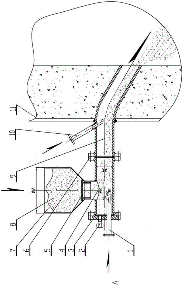
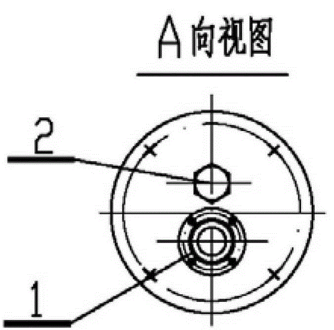
[0049] A solid material particle feeding device of the present invention, wherein the diameter of the feeding pipe 4 is 108 mm, and the diameter of the main blowing pipe 1 is 32 mm. One end of the main blowing pipe 1 is connected to the conveying gas generating device, and the other end extends into the feeding pipe 4 . The center line of the A-direction section of the feeding pipe 4 and the A-direction section of the main air blowing pipe are perpendicular to the horizontal line and the distance between the center line of the two centers is equal to the diameter radius of the feeding pipe 4 and the diameter radius of the main air blowing pipe 1. Poor, that is, the distance between the two centers of the center line is equal to 38mm. Wherein the main blowing pipe 1 extends into the part of the feeding pipe 4, the front end of the air outlet is flush with the side of the feeding port of the hopper 7 near the end of the feeding pipe 4. The plane where the end slit of the air ou...

Embodiment 2

[0051] Another solid material feeding device of the present invention, wherein the diameter of the feeding pipe 4 is 100 mm, and the diameter of the main blowing pipe 1 is 30 mm. One end of the main blowing pipe 1 is connected to the conveying gas generating device, and the other end extends into the feeding pipe 4 . The center line of the A-direction section of the feed pipe 4 and the A-direction section of the main blowing pipe are perpendicular to the horizontal line and the distance between the centerlines of the two centers is less than the difference between the radius of the feed pipe 4 and the main blowing pipe 1 radius. In this embodiment, the distance between the two centerlines is 30mm. Wherein the main blowing pipe 1 extends into the part of the feeding pipe 4, the front end of the air outlet is flush with the side of the feeding port of the hopper 7 near the end of the feeding pipe 4. The end cutout plane of the air outlet of the main blowing pipe 1 forms an angl...

Embodiment 3

[0053] Another solid material feeding device of the present invention, wherein the diameter of the feeding pipe 4 is 120 mm, and the diameter of the main blowing pipe 1 is 40 mm. One end of the main blowing pipe 1 is connected to the conveying gas generating device, and the other end extends into the feeding pipe 4 . The center line of the A-direction section of the feed pipe 4 and the A-direction section of the main blowing pipe are perpendicular to the horizontal line and the distance between the centerlines of the two centers is less than the difference between the radius of the feed pipe 4 and the main blowing pipe 1 radius. In this embodiment, the distance between the centerlines is 35 mm. Wherein the main blowing pipe 1 extends into the part of the feeding pipe 4, the front end of the air outlet is flush with the side of the feeding port of the hopper 7 near the end of the feeding pipe 4. The plane of the cutout at the end of the air outlet of the main blowing pipe 1 fo...


PUM


Abstract

The invention relates to a pneumatic solid particle feeding system which comprises a main blowing pipe, a feeding pipe and a hopper. The feeding pipe is used for conveying solid particles from the hopper, and the main blowing pipe is used for providing conveying air for conveying the solid particles for the feeding pipe. The pneumatic solid particle feeding system is characterized in that an end notch of an air outlet of the main blowing pipe is flush with the side, close to the end of the feeding pipe, of a discharging opening of the hopper, and at least part of the end notch of the air outlet of the main blowing pipe inclines, so that the conveying air blown by the main blowing pipe has a vector in at least one other direction besides the horizontal direction. By means of the pneumatic solid particle feeding system, the shapes of solid materials can be kept good, and the pipeline blocking phenomenon is avoided. The pneumatic solid particle feeding system is directly connected with an inlet pipe of a device reactor through the feeding pipe in a sealed mode, and therefore the continuous material conveying process can be achieved, energy consumption is lowered, and environment pollution is avoided.

Description

technical field [0001] The invention relates to a material conveying device, in particular to a solid particle pneumatic feeding system. Background technique [0002] At present, in the high-temperature refining and purification devices of various solid particles (especially mineral particles), due to the high-temperature environment in the equipment and the characteristics of solid substances, people mostly use screw / ribbon conveyors, high-level feed Due to the harsh conditions of the high-temperature equipment following the feeder, the inlet pipe and facilities of the feeder are often burned at high temperatures, and the crushing, dust, blockage, and melting of mineral particles during transportation, and People are more concerned about the accompanying problems such as high energy consumption and environmental pollution. [0003] Patent No. CN204247156U discloses a high-level material tank, and specifically discloses a cylinder body, the cylinder body is provided with an...

Claims


Application Information

Patent Timeline
Patent Type & Authority Applications(China)
IPC IPC(8): B65G53/12B65G65/40B65G53/52
Inventor 王涛卢成章刘鸿生陈文俊
Owner SICHUAN MINGXIN INVESTMENT
Why Eureka
Try Eureka