Femur fixture and set of femur fixtures

a femur fixture and a set technology, applied in the field of femur fixtures, can solve the problems of inability to simply address the situation and bone resorption at the resected surface, and achieve the effects of improving the contact between the femur fixture and the bone surface, increasing the stability of the inserted femur fixture, and promoting osseointegration

Inactive Publication Date: 2007-01-02
HIP
View PDF30 Cites 50 Cited by
  • Summary
  • Abstract
  • Description
  • Claims
  • Application Information

AI Technical Summary

Benefits of technology

[0026]According to preferred embodiments of the present invention, femur fixture further comprises a head section. The head section is provided with a collar abutting the tapered proximal section, which collar delimits the insertion of the femur fixture into bone tissue. Preferably, the surface of the collar facing the proximal section is inclined inwardly so as to mate with a resected bone tissue surface that has been given a correspondingly inclined shape. Preferably, the angle of inclination is within the range of 10°–20°, preferably approximately 15°. Alternatively, the surface of the collar facing the proximal section is given a concave shape, so as to mate with a convex bone tissue surface. Thereby, an improved contact between the femur fixture and the bone surface can be obtained.
[0027]Preferably, said collar surface is provided with radially spaced circular beads or grooves for increasing the stability of the inserted femur fixture and promote the osseointegration between the femur fixture and the bone tissue. Preferably, these beads have a height in the range of 0.1–0.5 mm, preferably in the range of 0.2–0.4 mm, and even more preferably approximately 0.3 mm.

Problems solved by technology

This lack of loading of the cortex at the resected surface of the femur by the intraosseous anchoring structure of the femur fixture can lead to bone resorption at the resected surface.
This situation is not able to be simply addressed by increasing the diameter of the cylindrical proximal section of the intraosseous anchoring structure of the WO93 / 16663 femur fixture since it would result in the threads of the cylindrical proximal section puncturing the cortex in the body of the femur neck or being dangerously close to puncturing the cortex due to the trumpet-like shape of the cortex in the femur neck.

Method used


Image

  • Femur fixture and set of femur fixtures
  • Femur fixture and set of femur fixtures
  • Femur fixture and set of femur fixtures

Examples


Embodiment Construction

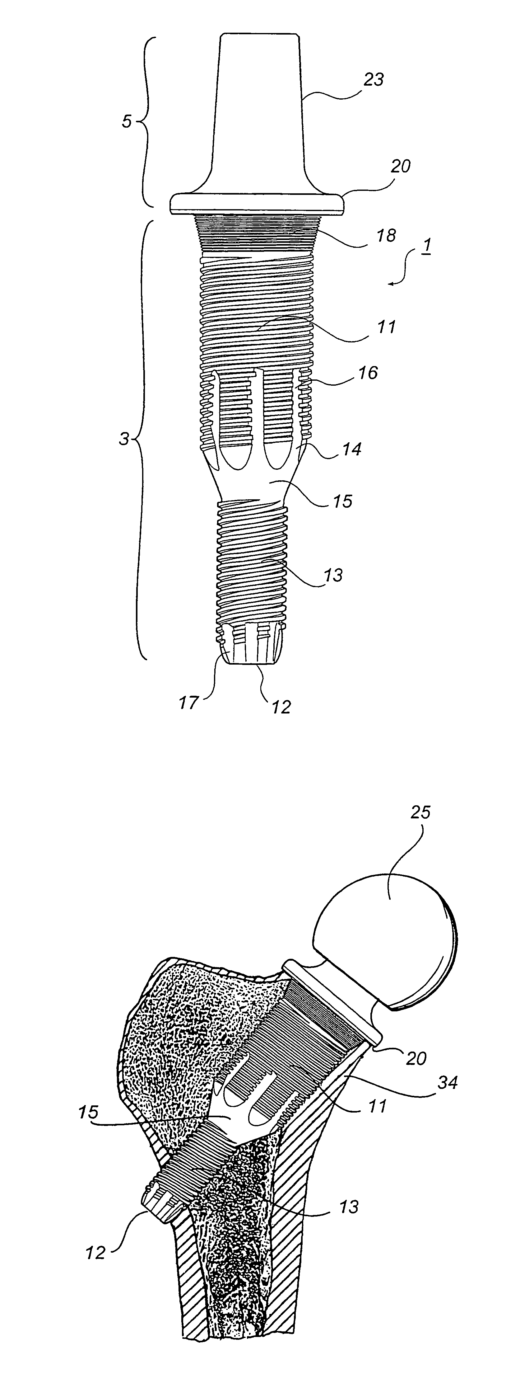
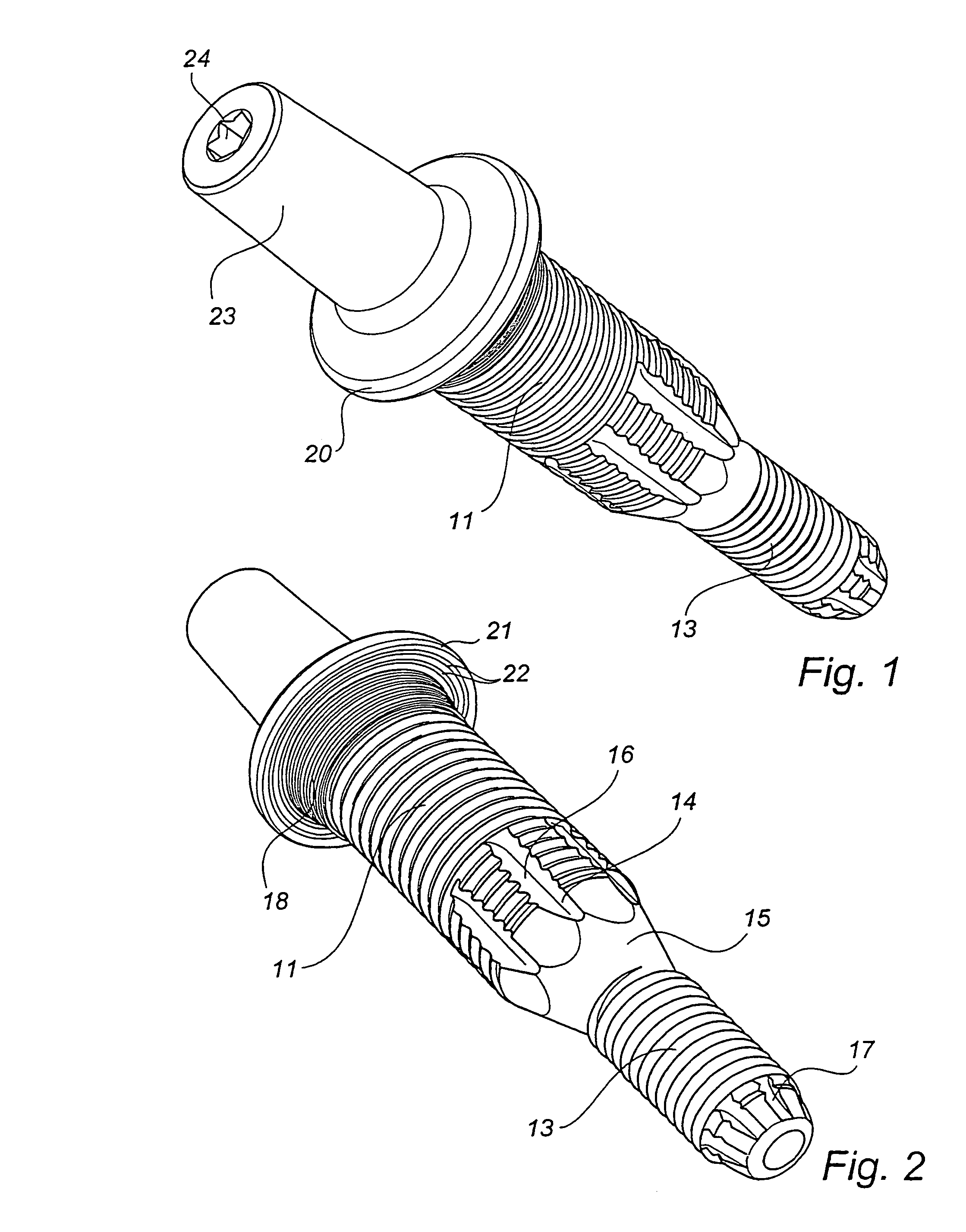
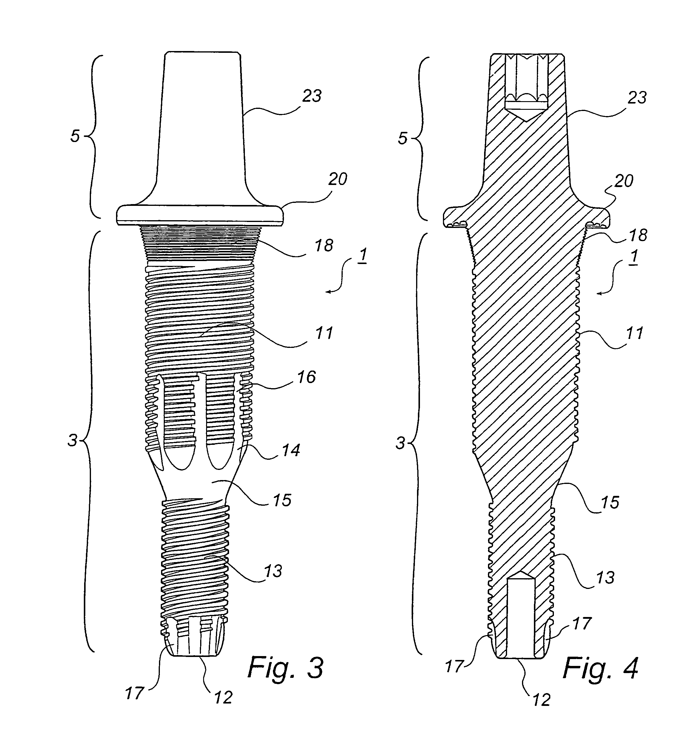
[0046]With reference to FIGS. 1–8, there is shown an integrally formed femur fixture 1 for a hip-joint prosthesis preferably made from commercially pure titanium and consisting of (i) an intraosseous anchoring section 3 of circular cross-section, and (ii) a head section 5. The anchoring section 3 is intended for insertion laterally into a cavity 30 of complementary profile (FIG. 7), said cavity 30 being drilled into the neck of a femur through a resected section 33 made by resection of the head of the femur. The head section 5 of the fixture, which will protrude from the resected section 33 when the intraosseous anchoring section 3 is located in the cavity 30 (FIG. 8), is arranged for supporting a ball 25 of the hip-joint prosthesis which interacts with the anatomical acetabular cavity or an acetabular part of the hip-joint prosthesis where a total hip-joint prosthesis is required.

[0047]As can be seen in FIGS. 1–3, the intraosseous anchoring section 3 has proximal and distal cylindr...


PUM


Abstract

A femur fixture for a hip-joint prosthesis comprising an intraosseous anchoring structure of a generally circular cross-section for screwing laterally into a complementary bore drilled laterally into the neck of a femur after resection of the femur head to an anchored position. The intraosseous anchoring structure has a proximal end, a distal end, a relatively short frusto-conical proximal section at the proximal end, and a proximal cylindrical section having a screw thread profile thereon. The proximal cylindrical section extends from the frusto-conical proximal section towards the distal end of the anchoring structure. The frusto-conical proximal section and the proximal cylindrical section each being dimensioned so as to bear against the cortex of the femur neck when the intraosseous anchoring structure is in the anchored position. The invention also relates to a set of such femur fixtures, wherein the frusto-conical proximal section and the proximal cylindrical section of each fixture in the set have different dimensions, whereby the fixture in the set having the frusto-conical proximal section and the proximal cylindrical section of correct size for abutting the cortex of the femur neck of a particular patient can be selected for use in that patient.

Description

[0001]This application is the national phase under 35 U.S.C. § 371 of PCT International Application No. PCT / SE00 / 01945 which has an International filing date of Oct. 6, 2000, which designated the United States of America.FIELD OF THE INVENTION[0002]The present invention relates to a femur fixture for a hip-joint prosthesis comprising an intraosseous anchoring structure of a generally circular cross-section adapted for screwing laterally into a complementary bore drilled laterally into the neck of a femur after resection of the femur head to an anchored position. The invention also relates to a set of such femur fixtures.BACKGROUND OF THE INVENTION[0003]A femur fixture of the aforementioned type is disclosed in Applicant's prior International patent application publication WO93 / 16663. In this femur fixture the intraosseous structure has a screw threaded cylindrical section at the proximal end. The use of a cylindrical proximal section in the intraosseous structure of the femur fixtur...

Claims


Application Information

Patent Timeline
Patent Type & Authority Patents(United States)
IPC IPC(8): A61F2/36A61F2/28A61B17/74A61B17/88A61F2/00A61F2/30A61F2/32A61F2/46
CPCA61F2/3601A61B17/742A61F2310/00023A61F2002/30113A61F2002/30118A61F2002/30171A61F2002/3021A61F2002/30215A61F2002/30233A61F2002/30327A61F2002/30332A61F2002/30795A61F2002/30827A61F2002/30828A61F2002/30858A61F2002/30859A61F2002/30864A61F2002/30871A61F2002/30874A61F2002/30879A61F2002/30906A61F2002/3611A61F2002/3625A61F2002/3633A61F2002/365A61F2002/369A61F2220/0033A61F2230/0006A61F2230/005A61F2230/0067A61F2230/0069A61F2250/0039A61F2002/3631A61F2002/30878A61F2002/30873
Inventor ALBREKTSSON, TOMASCARLSSON, LARSJACOBSSON, MAGNUSMACDONALD, WARRENWENNBERG, STIG
Owner HIP
Why Eureka
Try Eureka