
Liquid additive slow-release apparatus driven by a filter pressure gradient

a slow-release apparatus and liquid additive technology, applied in the direction of liquid displacement, lubricant mounting/connection, separation process, etc., can solve the problems of increasing wear on the diesel engine, significant harm to the overall operation, performance and efficiency of the engine and even to the environment, and difficulty in maintaining a constant or desired level of additive in the fuel

Active Publication Date: 2007-01-02
CUMMINS FILTRATION INC
View PDF24 Cites 69 Cited by
  • Summary
  • Abstract
  • Description
  • Claims
  • Application Information

AI Technical Summary

Benefits of technology

The present invention provides a novel filter assembly with a unique design that allows for the addition of a liquid additive to the liquid flowing through the filter. The filter assembly includes a housing with two regions of different fluid dynamic pressure, a filter element, and a container with two capillary tubes. The liquid additive can be deposited in the interior region of the container and will flow out of the container when there is a difference in fluid dynamic pressure between the two regions. The invention also provides a method for inducing the liquid additive to flow out of the container. The technical effects of the invention include improved fuel, oil, lubricant, and coolant performance, as well as improved filter efficiency and durability.

Problems solved by technology

The resulting low sulfur content diesel fuel caused increased wear on the diesel engine and, in particular, to the fuel pump and injectors, which in turn caused significant harm to the overall operation, performance, and efficiency of the engine and even to the environment.
It is difficult to maintain a constant or desired level of the additive in the fuel.
While many bottled fuel additives are commercially available, often operators do not consistently add the additive with each fill-up—the additive might not be readily available or the operator may forget to include the additive.
Combining the additive with fuel in the fuel tank may not reliably provide a homogenous fuel / additive mixture.
Fuel tanks do not include reliable methods for mixing fuel.

Method used


Image

  • Liquid additive slow-release apparatus driven by a filter pressure gradient
  • Liquid additive slow-release apparatus driven by a filter pressure gradient
  • Liquid additive slow-release apparatus driven by a filter pressure gradient

Examples


Embodiment Construction

[0031]For the purposes of promoting an understanding of the principles of the invention, reference will now be made to the embodiments illustrated herein, and specific language will be used to describe the same. It will nevertheless be understood that no limitation of the scope of the invention is thereby intended. Any alterations and further modifications of the described filters, cartridges, and processes, and any further applications of the principles of the invention as described herein, are contemplated as would normally occur to one skilled in the art to which the invention relates.

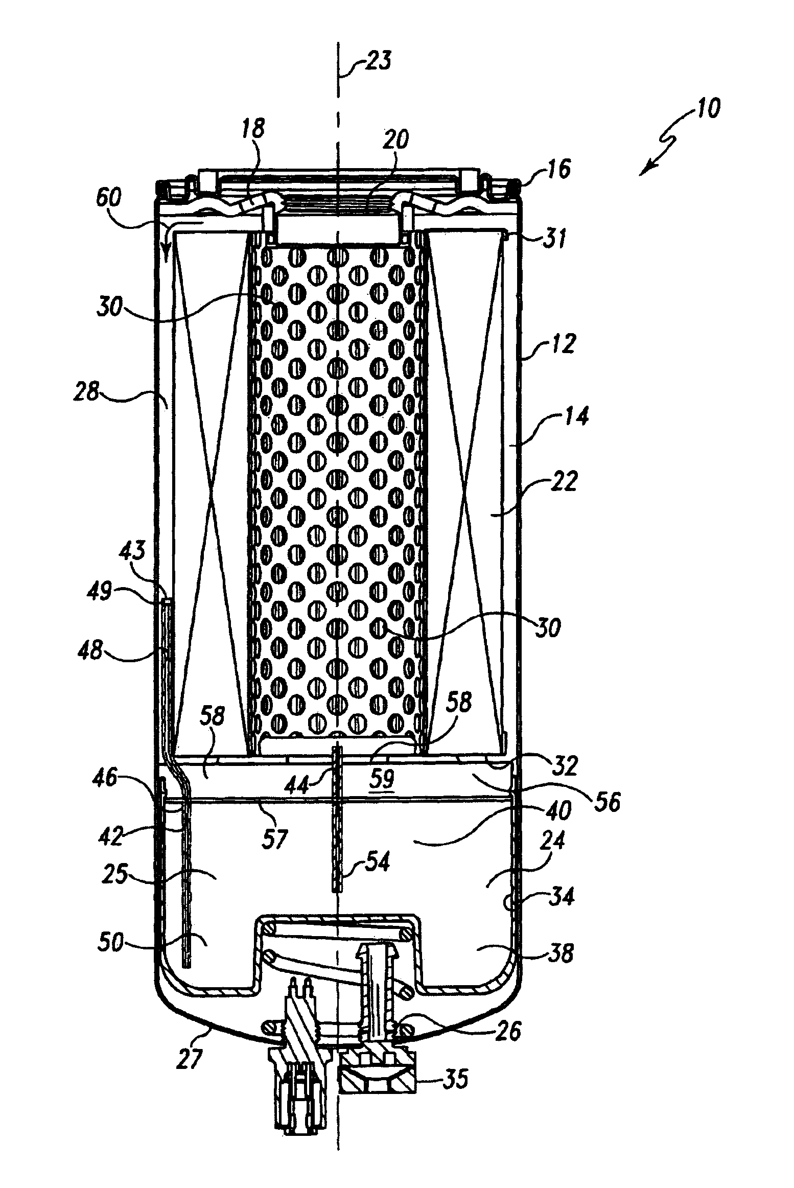
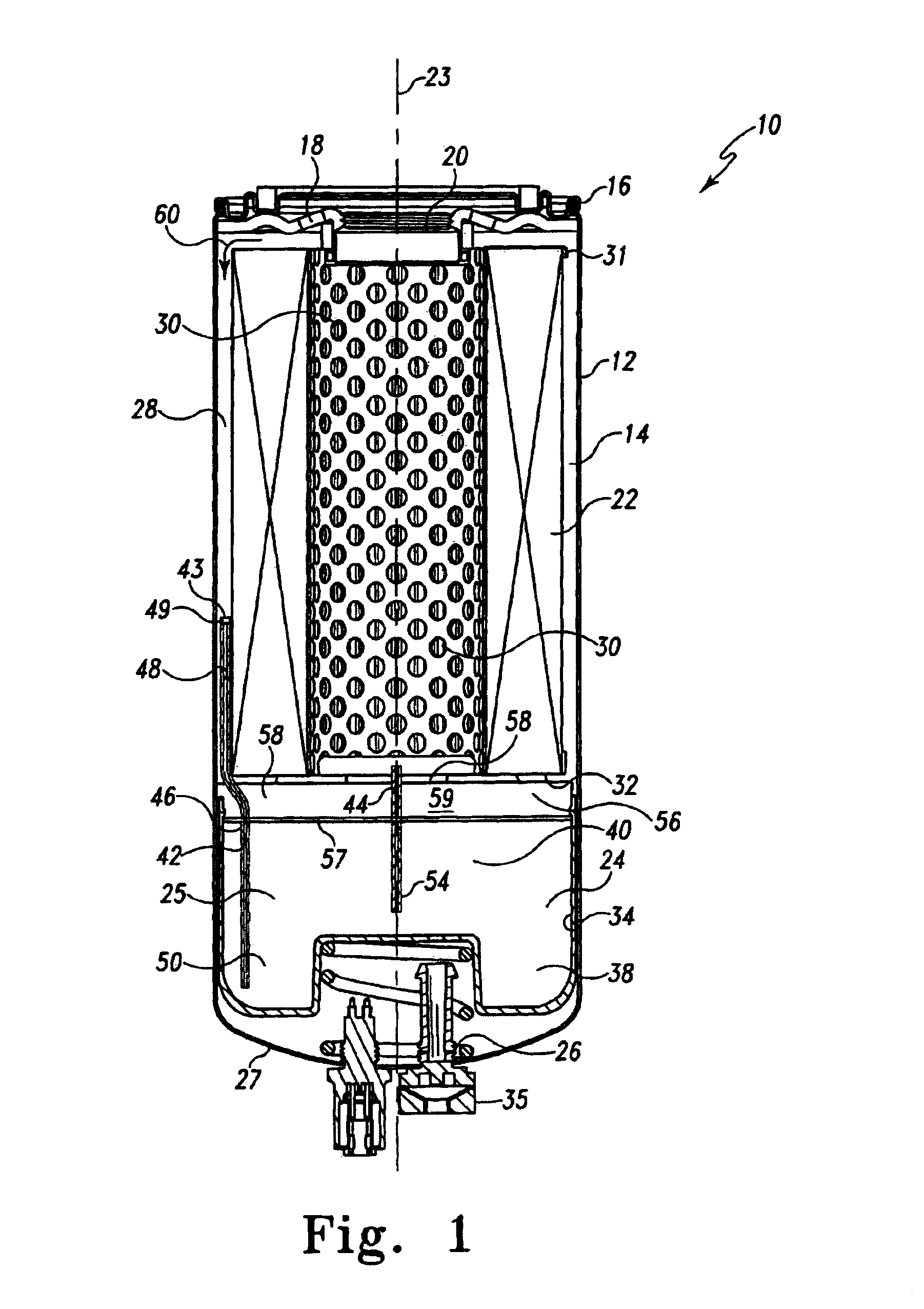
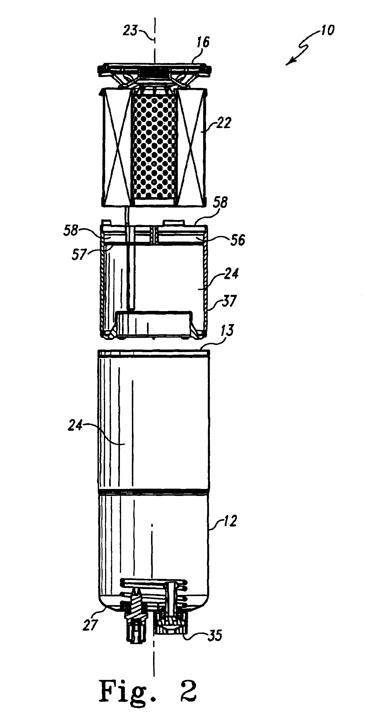
[0032]FIG. 1 is a cross-sectional view of a filter assembly 10 provided in accordance with the present invention. FIG. 2 is an exploded, cross-sectional view of the same filter assembly 10. Filter assembly 10 includes a housing or outer casing 12 defining an interior chamber 14. A nut plate 16 is secured across an open end 13 of casing 12. Nut plate 16 provides at least one inlet 18, preferably a pl...


PUM

PropertyMeasurementUnit
diffusion coefficientaaaaaaaaaa
pressureaaaaaaaaaa
lengthaaaaaaaaaa

Abstract

The present invention provides a filter assembly containing a filter element and a container as a depot for a liquid additive. The container can include an inlet and an outlet, which are configured to allow a liquid to flow into the container mix with the contained additive and then flow out into the system. It has been observed that a liquid flowing through a filter assembly exhibits a pressure gradient within the filter. Consequently, the inlets and outlets to the container can be positioned to take advantage of the pressure gradient to enhance the addition of the additive to the liquid in the filter assembly.

Description

BACKGROUND OF THE INVENTION[0001]The present invention is directed to a liquid filtration system and to a method of treating the liquid in the enclosed system.[0002]Filter assemblies are commonly used to protect combustion engines by filtering out contaminants and thereby preventing damage to the engine and other downstream components such as valves, fuel injectors, fuel lines, and related other components. To maintain engine performance and reliability, the filter assemblies must be replaced, often as frequently as every 2,000 to 4,000 vehicle miles.[0003]It can be equally important to add agents to the fuel to reduce damage to the engine and related downstream components and / or to enhance the performance of the engine. For example, since the early 1990's diesel fuel producers have significantly reduced the sulfur content in diesel fuel to reduce the environmental harm that was attributed to the burning of high sulfur content fuels. However, the naturally occurring sulfur in the di...

Claims


Application Information

Patent Timeline
Patent Type & Authority Patents(United States)
IPC IPC(8): B01D27/04B01D1/00B01D35/00B01D37/02
CPCB01D37/025F02M37/22F02M25/00F02M37/24F02M37/34F02M37/36F02M37/42
Inventor HERMAN, PETER K.MARTIN, HAROLD R.BAGCI, ISMAIL C.
Owner CUMMINS FILTRATION INC
Learn More