Method and apparatus for scanning a key or button matrix

a key or button matrix and key technology, applied in the direction of coding, instruments, pulse techniques, etc., can solve the problems of consuming too much power, consuming 20–30% of the overall current consumption of the keyboard, and existing methods of keyboard matrix scanning are slow

Active Publication Date: 2007-01-02
MONTEREY RES LLC
View PDF2 Cites 43 Cited by
  • Summary
  • Abstract
  • Description
  • Claims
  • Application Information

AI Technical Summary

Problems solved by technology

This amounts to 20–30% of the overall current consumption of the keyboard.
These existing methods of keyboard matrix scanning are slow, consume too much power, and prevent the MCU from performing other tasks for a significant period of time while scanning the matrix.

Method used


Image

  • Method and apparatus for scanning a key or button matrix
  • Method and apparatus for scanning a key or button matrix
  • Method and apparatus for scanning a key or button matrix

Examples


Embodiment Construction

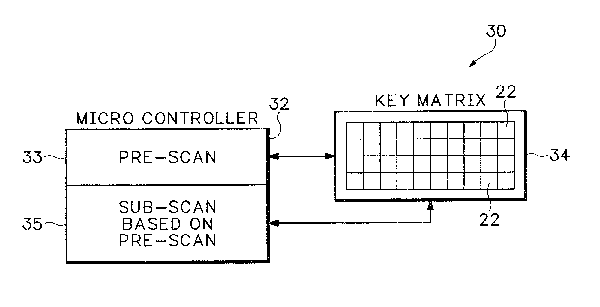
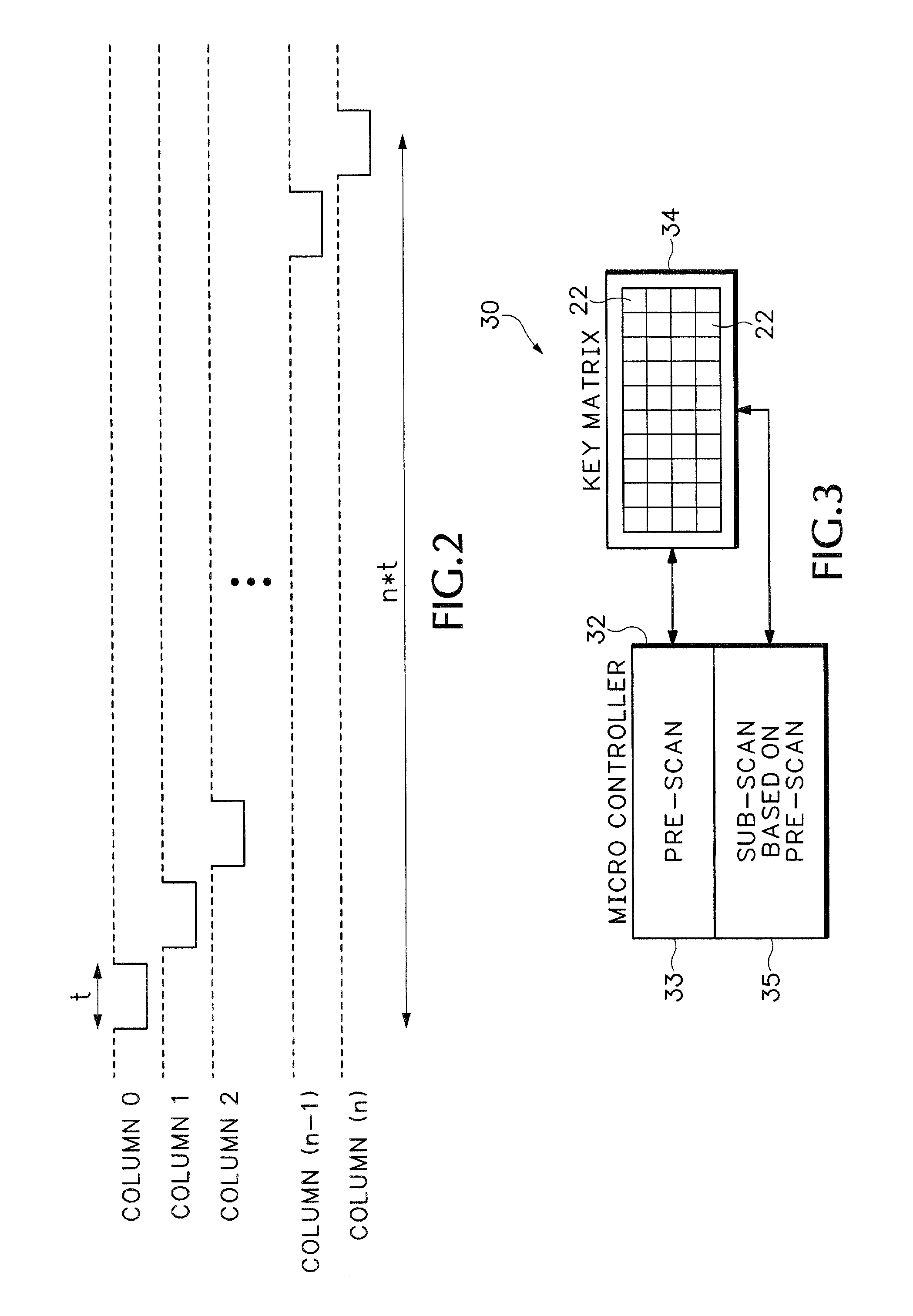
[0026]FIG. 3 shows an improved key matrix scanning system 30. The scanning system 30 can increase battery life of a wireless keyboard and other types of remote control and battery operated devices by reducing the time required for a Microcontroller Unit (MCU) 32 to scan a key matrix 34.

[0027]The MCU 32 can be any type of programmable processing device. In other embodiments, the MCU 32 is firmware such as a Programmable Logic Device (PLD) that is hard coded to perform the operations described below. The key matrix 34 can be any circuitry used for sensing depression of keys or buttons on a user control device. The terms keys and buttons are used interchangeably in the description below and refer to any type of actuation device used for communicating a user input to a computing device.

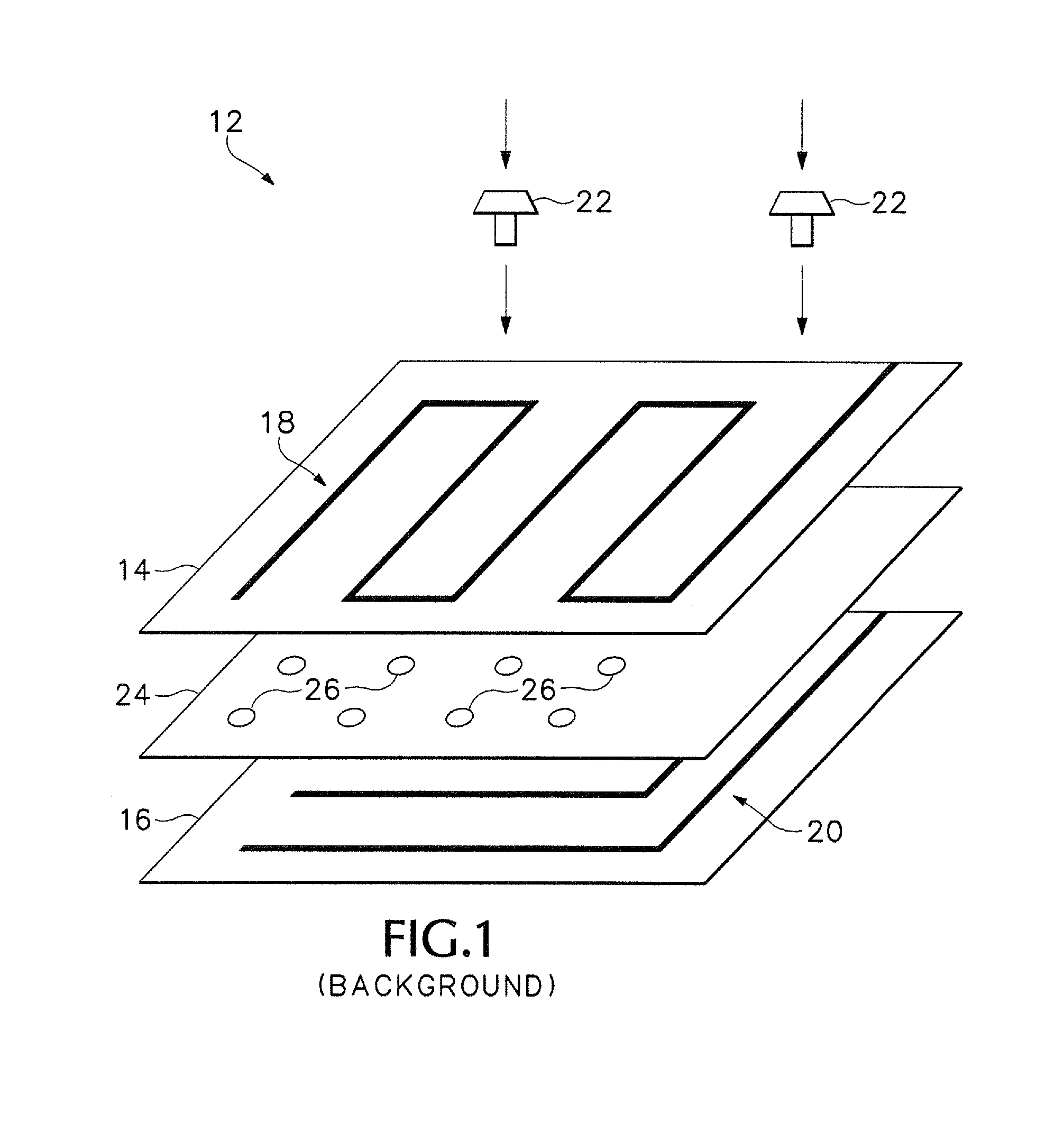
[0028]Typically only one button 22 is pressed at a time on a keyboard or keypad used with the key matrix 34. In other cases, two keys 22 are pressed at the same time. Only in rare cases, amounting to a ne...


PUM


Abstract

An improved key matrix scanning technique conducts a first pre-scan on a first array of connections in a key matrix to identify any activated keys or buttons associated with the first array. A second sub-scan is conducted on a second array of connections in the key matrix but only for the connections in the first array that are detected as having activated keys.

Description

BACKGROUND[0001]FIG. 1 shows how a typical keyboard matrix 12 is constructed. Two thin sheets 14 and 16 of plastic or polymer material have printed conductive traces 18 and 20, respectively. The traces 18 and 20 are arranged such that when pressure is applied at certain locations, such as when keys 22 on a keyboard are pressed, one trace on sheet 14 makes an electrical connection with one trace 20 at the corresponding location on the other sheet 16.[0002]Typically, the sheets 14 and 16 are separated by a third sheet 24 with no printed traces. The third sheet 24 includes holes 26 aligned with the positions of buttons 22. When no pressure is applied to the area above the holes 26, the conductive traces 18 and 20 do not make contact. When one of the keys 22 is pressed, one of the traces 18 on sheet 14 is pushed through the corresponding hole 26 making an electrical contact with one of the traces 20 on sheet 16. The electrical cross-connection between the trace 18 and the trace 20 is as...

Claims


Application Information

Patent Timeline
Patent Type & Authority Patents(United States)
IPC IPC(8): H03M11/20
CPCH03M11/20G06F3/02G06F3/023H03K17/94
Inventor WRIGHT, DAVID G.ASBURY, RAY
Owner MONTEREY RES LLC
Why Eureka
Try Eureka