
Systems and methods for forming a reduced-glare image

Active Publication Date: 2007-01-02
L 1 IDENTITY SOLUTIONS OPERATING CO INC
View PDF5 Cites 39 Cited by
  • Summary
  • Abstract
  • Description
  • Claims
  • Application Information

AI Technical Summary

Benefits of technology

[0008]The present invention addresses the above described limitations of identifying an object from an image of the object. The present invention describes a method and a system that reduce the effects of glare on an object when forming an image of the object.
[0011]In another aspect of the present invention, a method for forming an image of an object that has reduced glare is provided. The method includes the steps of acquiring a first image of an object while illuminated with a first light source and acquiring a second image of the object while illuminated with a second light source. The method compares intensity values for selected pixels from each of the images and identifies the pixels from the comparison with a lower intensity value. Using the identified pixels with the lower intensity value a composite image is formed of the object having reduced glare.

Problems solved by technology

Traditional methods of identifying individuals, such as looking up a suspect in a book of mug shots, are slow, tedious, and prone to human error.
For example, during the “look-up” phase, when a security officer attempts to match the face of a suspect to a depository of photographs of wanted criminals, there is the risk that a photograph of a wanted individual is overlooked in error.
Additionally, in a setting where a large number of people are present, there is always the risk that a wanted criminal might get lost in the crowd, thus avoiding detection by security personnel.
While useful in many circumstances, such methods, however, suffer from being intrusive because they require individuals to perform some act like signing or staining their thumb, or showing a document.
Aside from the inconvenience of having to perform these acts, another drawback of such identification methods is that it gives the individual an opportunity to thwart the method by, for example, forging a signature or a passport.
For example, a common problem, especially for individuals who wear glasses, is the effect of glare from the glasses during imaging of the individual.
If the resulting facial image is poor due to glare, subsequent identify of the individual from the facial image becomes significantly burdensome.

Method used


Image

  • Systems and methods for forming a reduced-glare image
  • Systems and methods for forming a reduced-glare image
  • Systems and methods for forming a reduced-glare image

Examples


Embodiment Construction

[0019]FIGS. 1–5, wherein like parts are designated by like reference numerals throughout, illustrate exemplary embodiments of a system and method suitable for recognizing an individual. Although the present invention is described with reference to the exemplary embodiments illustrated in the Figures, it should be understood that many alternative forms could embody the present invention. One of ordinary skill in the art will additionally appreciate different ways to alter the parameters of the embodiments disclosed, such as the size, language, interface, or type of elements or materials utilized, in a manner still in keeping with the spirit and scope of the present invention.

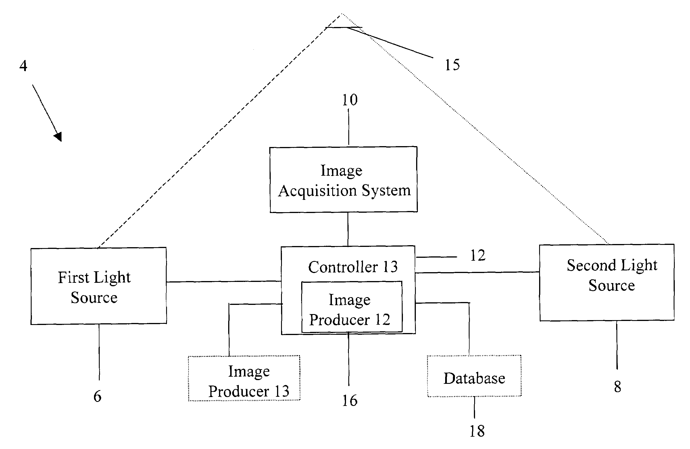
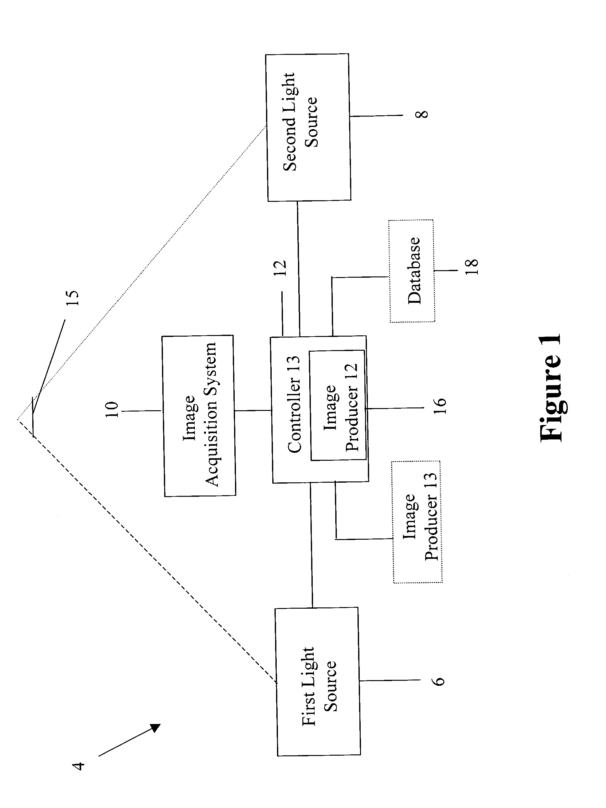
[0020]Referring to FIG. 1, an imaging system 4 for producing a reduced glare image suitable for use in identifying an object from the image is shown. The imaging system 4 includes a first light source 6, a second light source 8, an image acquisition device 10, and a controller 12. The imaging system 4 optionally ...


PUM


Abstract

A method and system are disclosed for producing a reduced-glare image. The method and system use at least two light sources located a selected distance apart from each other. An image acquisition device acquires a first image of an object using illumination from the first light source, but not the second. Then the image acquisition device acquires a second image of the object using illumination from the second light source, but not the first. The two images, having glare at different pixel locations, are then used to form a reduced-glare image.

Description

TECHNICAL FIELD[0001]The present invention relates generally to imaging of an object, and more specifically, relates to systems and methods for reducing the effects of glare in an image of the object.BACKGROUND[0002]With the present security concerns in the world, there is a heightened need for systems and methods that can recognize or identify individuals in various settings. For example, security needs often dictate that an individual be correctly identified before the individual is permitted to perform some task, such as using an automated teller machine (ATM) or entering an airplane, a federal or state facility, an airport location, or other restricted area.[0003]Traditional methods of identifying individuals, such as looking up a suspect in a book of mug shots, are slow, tedious, and prone to human error. For example, during the “look-up” phase, when a security officer attempts to match the face of a suspect to a depository of photographs of wanted criminals, there is the risk ...

Claims


Application Information

Patent Timeline
IPC IPC(8): G09G5/00G06V10/141
CPCG03B15/03G06K9/00221G06K9/036G06K9/2027G06T5/008G06T5/50G06T2207/10152G06T2207/20221G06T2207/30201G06V40/16G06V10/993G06V10/141G06T5/94
Inventor BERUBE, DENIS K.CUSACK, JR., FRANCIS J.EHN, DENNIS C.
Owner L 1 IDENTITY SOLUTIONS OPERATING CO INC
Learn More