Recording medium, recording method, reproduction method, recording apparatus and reproduction apparatus

a recording medium and recording method technology, applied in the field of optical disc mediums, can solve the problems of unstable signal reproduction systems for level-slicing, pll or the like, and the inability to read data recorded from the beginning position (start position) to the next frame area

Active Publication Date: 2007-01-02
PANASONIC CORP
View PDF17 Cites 32 Cited by
  • Summary
  • Abstract
  • Description
  • Claims
  • Application Information

AI Technical Summary

Problems solved by technology

Therefore, data recorded from the linking beginning position (start position) to the next frame area cannot be read since accurate bit synchronization cannot be realized.
Furthermore, when the low precision of linking causes the length of the frame area to be larger or smaller than the prescribed length, or when repeated linking recording in the same frame area degrades the signal in the frame area, signal reproduction systems for level-slicing, PLL or the like become unstable when the data recorded in and in the vicinity of the linking position is reproduced.
In the worst case, there is a possibility that data cannot be read in several frame areas after the linking position.
In such a case, error correction cannot be performed, which possibly generates a reading error.
However, the tolerance of less than one bit is difficult to realize and thus is impractical as the recording density of data is increased.

Method used


Image

  • Recording medium, recording method, reproduction method, recording apparatus and reproduction apparatus
  • Recording medium, recording method, reproduction method, recording apparatus and reproduction apparatus
  • Recording medium, recording method, reproduction method, recording apparatus and reproduction apparatus

Examples


example 1

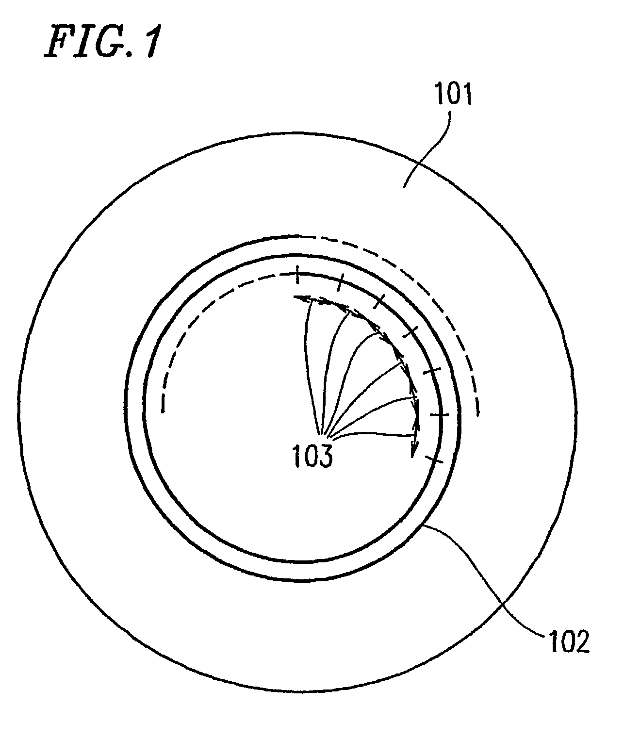
[0144]FIG. 1 shows a top view of a recordable optical disc medium (recording medium) 101 according to a first example of the present invention. On a recording surface of the optical disc medium 101, a recording track 102 (recording area) is formed in a spiral manner. The recording track 102 is divided into data blocks 103. In other words, on the recording surface of the optical disc medium 101, the data blocks 103 are continuously arranged in a circumferential direction to form the information track 102.

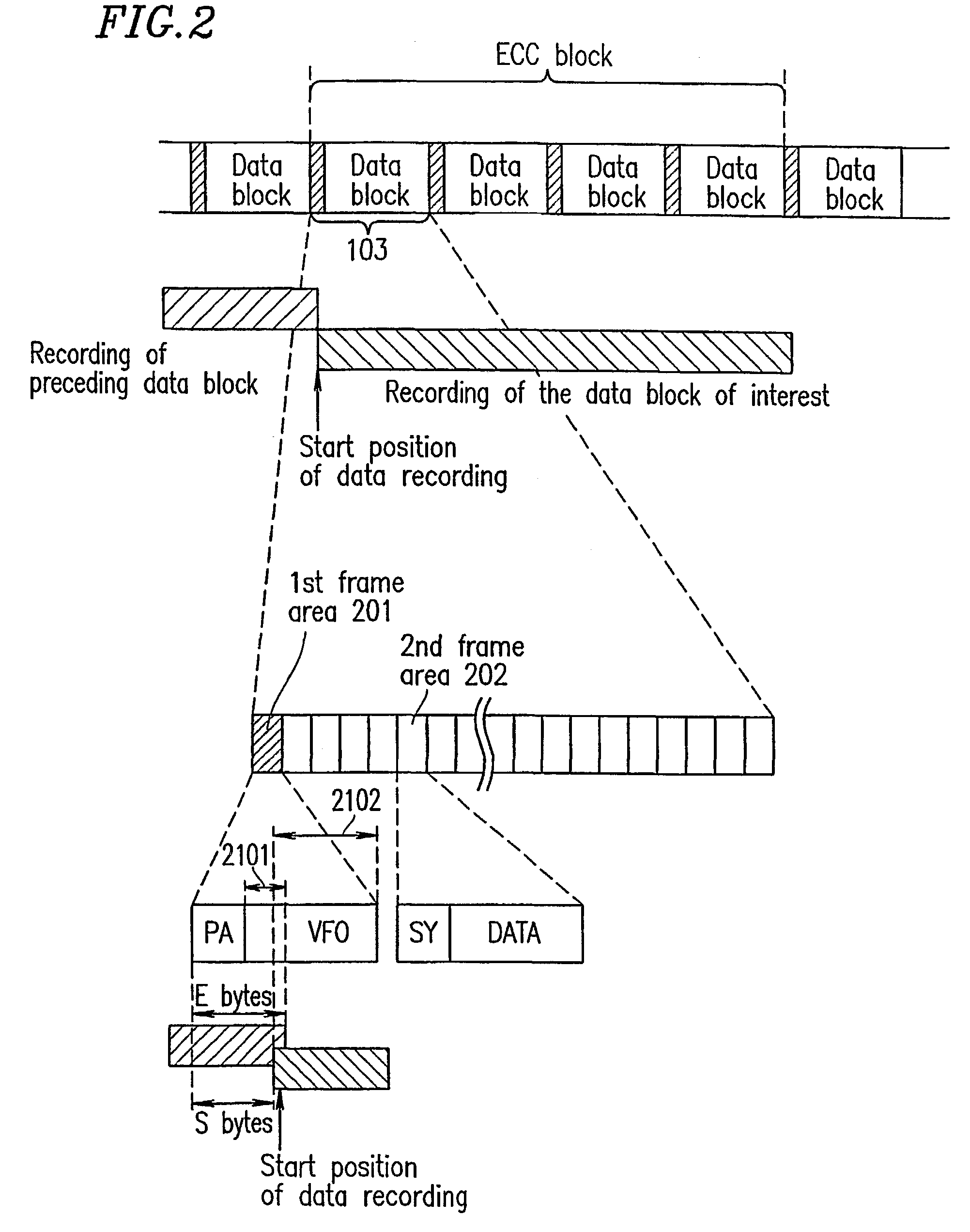
[0145]FIG. 2 shows a data format of the data blocks 103 of the optical disc medium 101. As shown in FIG. 2, each data block 103 includes a first frame area 201 at the start thereof and then a plurality of second frame areas 202 thereafter. The first frame area 201 and the second frame areas 202 form one data block 103. In FIG. 2, an area shown in the right is rearward to an area shown in the left.

[0146]Thus, the information track 102 of the optical disc medium 101 includes a pluralit...

example 2

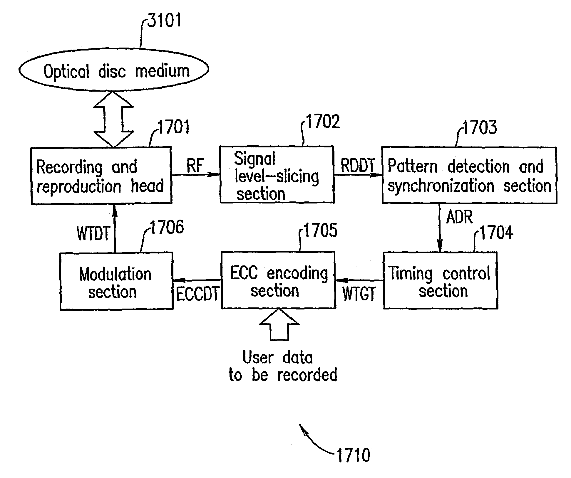
[0202]FIG. 8 shows a top view of a recordable optical disc medium (recording medium) 3101 according to a second example of the present invention. As shown in FIG. 8, on a recording surface of the optical disc medium 3101, a recording track 3102 (recording area) is formed in a spiral manner. The recording track 3102 is divided into data blocks 301. In other words, on the recording surface of the optical disc medium 3101, the data blocks 301 are continuously arranged in a circumferential direction to form the information track 3102.

[0203]FIG. 9 shows an example of a data format of the optical disc medium 3101 in the second example of the present invention. In FIG. 9, identical elements as those described above with reference to FIG. 2 bear identical reference numeral therewith and will not be described in detail. In FIG. 9, an area shown in the right is rearward to an area shown in the left.

[0204]As shown in FIG. 9, each data block 301 includes a first frame area 201 and 8 sectors 310...

example 3

[0270]FIG. 23 shows a top view of a recordable optical disc medium 401 according to a third example of the present invention. On a recording surface of the optical disc medium 401, a recording track 402 is formed in a spiral manner. The recording track 402 is divided into data blocks 403. In other words, on the recording surface of the optical disc medium 401, the data blocks 403 are continuously arranged in a circumferential direction to form the information track 402.

[0271]FIG. 24 shows a data format of the data blocks 403 of the optical disc medium 401 (FIG. 23) according to the third example of the present invention. As shown in FIG. 24, a first frame area 501 is located at the start of each data block 403, and a plurality of second frame areas 502 are located subsequent to the first frame area 501. The first frame area 501 and the plurality of second frame areas 502 form one data block 403. In FIG. 24, an area shown in the right is rearward to an area shown in the left.

[0272]Th...


PUM

PropertyMeasurementUnit
recording areaaaaaaaaaaa
areaaaaaaaaaaa
code distanceaaaaaaaaaa

Abstract

A recording medium comprising a recording area, the recording area includes a first area and a second area, the first area includes a frame area, the frame area includes an area in which a second synchronization code sequence and at least a portion of data are to be recorded, and the second area includes an area in which a third synchronization code sequence and a fourth synchronization code sequence are to be recorded.

Description

TECHNICAL FIELD[0001]The present invention relates to an optical disc medium allowing high density data recording, and a method and apparatus for recording data on or reproducing data from the optical disc medium.BACKGROUND ART[0002]Recently, the recording density of optical disc media has been rapidly increasing. In the case of optical disc media allowing digital data recording, data recording, reproduction and management are generally performed in units of blocks, each block having a prescribed byte length. (Such a block will be referred to as a “data block”.) Each data block is given address information. Data recording and reproduction are performed with reference to the address information.[0003]For recording data on an optical disc medium, user data such as, for example, audio, video and computer data to be stored is provided with redundant data such as, for example, an error correction code (parity code) used for detecting or correcting a data error when the stored data is rea...

Claims


Application Information

Patent Timeline
Patent Type & Authority Patents(United States)
IPC IPC(8): G11B7/004G11B7/00G11B7/0045G11B7/007G11B20/10G11B20/12G11B20/14G11B20/18G11B27/30
CPCG11B7/00454G11B7/00736G11B7/00745G11B20/10G11B20/10203G11B20/1217G11B20/1403G11B20/1833G11B27/3027G11B2220/2562G11B20/1426G11B2007/0006G11B2020/1222G11B2020/1225G11B2020/1232G11B2020/1277G11B2020/1287G11B2220/20G11B2220/216G11B2220/2537G11B7/00456G11B7/007
Inventor GUSHIMA, TOYOJIFURUMIYA, SHIGERUISHIDA, TAKASHIISHIBASHI, HIROMICHIDEGUCHI, HIRONORINAKAMURA, ATSUSHIMINAMINO, JUNICHIUSUI, MAKOTONAKAJIMA, TAKESHI
Owner PANASONIC CORP
Why Eureka
Try Eureka