Method for predicting a fill-up level of a buffer in an ATM network element

Inactive Publication Date: 2007-01-02
NOKIA CORP
View PDF7 Cites 11 Cited by
  • Summary
  • Abstract
  • Description
  • Claims
  • Application Information

AI Technical Summary

Benefits of technology

[0014]Thus, with the present invention being implemented in an ATM network and/or an ATM network element, connection admission control can be improved. Particularly, due to the provision of the new parameter of the slope of the fill-up level curve,

Problems solved by technology
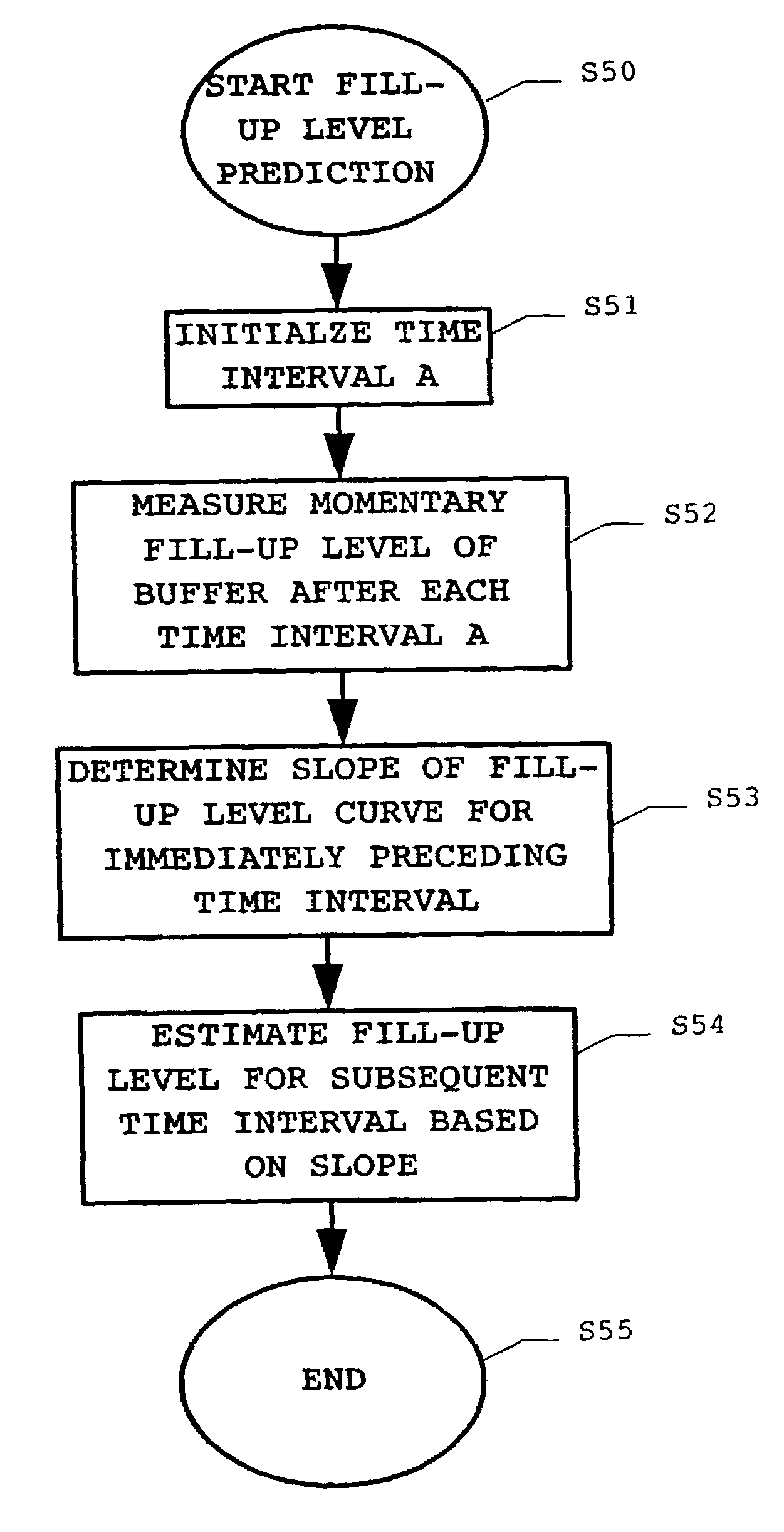
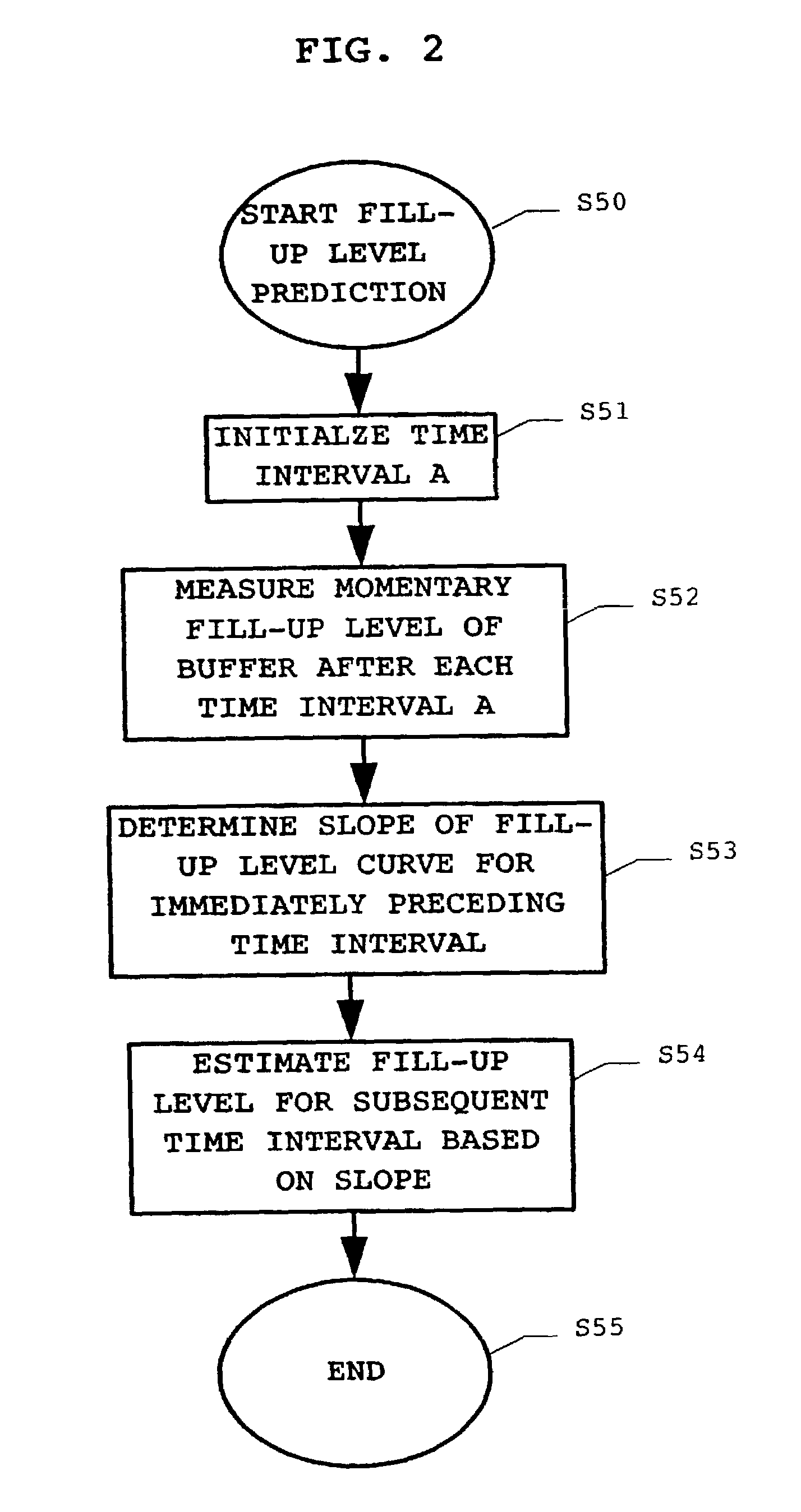
However, with an increasing data amount to be handled and/or transmitted, the buffer capacity of the ATM network element becomes a limiting factor for the increase in the amount of transmitted data.
However, if the method is a very effective one, i.e., one which may exploit the maximum capacity of the network, it will presumably be too slow as it needs too many calculations.
In contrast thereto, i

Method used


Image

  • Method for predicting a fill-up level of a buffer in an ATM network element
  • Method for predicting a fill-up level of a buffer in an ATM network element
  • Method for predicting a fill-up level of a buffer in an ATM network element

Examples


Embodiment Construction

[0024]The present invention is now described in greater detail with reference to the drawings.

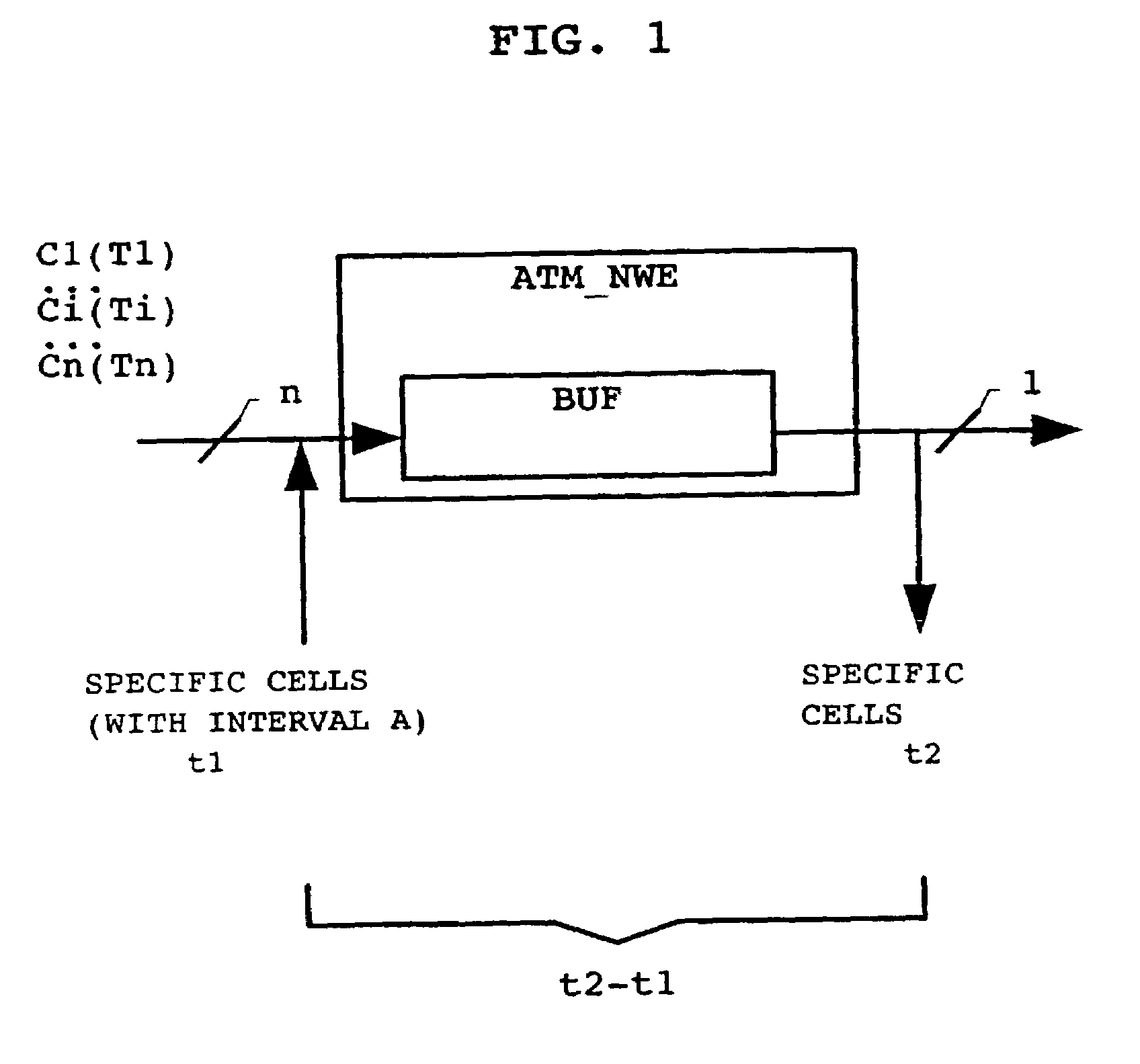
[0025]FIG. 1 shows a simplified and schematic block diagram of an ATM network element ATM_NWE with reference to which the principles of buffer delay measurements are subsequently explained. As illustrated, the ATM network element ATM_NWE is modeled as comprising a buffer BUF. The ATM network element is illustrated as handling a number n of ongoing transmission connections T1, . . . Ti, . . . , Tn, and for each connection cells C1, . . . , Ci, . . . , Cn are input to said ATM network element at respective (possibly different) input cell rates. At the output side, the ATM network element outputs a stream of ATM cells with a predetermined output cell rate.

[0026]In order to measure the buffer's fill-up level, one of the most reasonable methods resides in the use of specific cells. The specific cells are introduced into the cell stream at the input side of the ATM network element and are read at...


PUM


Abstract

The present invention proposes a method for predicting a fill-up level of a buffer in an ATM network element, wherein for a respective one of at least one ongoing transmission connection (T1, . . . Ti, . . . Tn) via said ATM network element (ATM_NWE), cells (C1, . . . , Ci, . . . , Cn) are input to said buffer (BUF) with a respective input cell rate, and said ATM network element outputs said cells at a predetermined output cell rate; comprising the steps of: measuring a momentary fill-up level of said buffer after each respective time interval (A), determining a slope of the fill-up level of said buffer for the immediately preceding time interval, and estimating the fill-up level of said buffer to be reached after the subsequent time interval based on said slope of the fill-up level for the immediately preceding time interval. Also, the present invention proposes a method for connection admission control for such an ATM network element said method making use of the proposed scheme for predicting a fill-up level of said buffer in said ATM network element, and further denies and/or accepts a new transmission connection requested to be handled by said ATM network element based on the predicted fill-up level of said buffer. Still further, the present invention aims at correspondingly adapted control devices within an ATM network.

Description

PRIORITY CLAIM[0001]This is a national stage of PCT application No. PCT / EP99 / 08499, filed on Nov. 5, 1999. Priority is claimed on that application.FIELD OF THE INVENTION[0002]The present invention relates to a method for predicting a fill-up level of a buffer in an ATM network element, and more particularly, to such a method which can be used in connection with a connection admission control method for an ATM network element comprising a buffer.BACKGROUND OF THE INVENTION[0003]In recent years, the development of telecommunication networks has made large progress. Also, the traffic capacity and thus the data amount handled by such networks has considerably increased. One approach to cope with such a large data amount while still providing a high speed data transmission within such networks is to use the generally known ATM transmission concept (Asynchronous Transfer Mode).[0004]In brief, according to the well known principles of ATM, the data to be transmitted are grouped into cells ...

Claims


Application Information

Patent Timeline
IPC IPC(8): G06F11/00H04L12/26H04L12/28H04L12/56H04L12/70H04Q11/04
CPCH04Q11/0478H04L2012/5632H04L2012/5681H04L2012/5649
Inventor SAARI, JARMO
Owner NOKIA CORP
Why Eureka
Try Eureka