Micromechanical component having a test structure for determining the layer thickness of a spacer layer and method for manufacturing such a test structure

a micromechanical component and test structure technology, applied in the direction of resistance/reactance/impedence, electrical/magnetic thickness measurement, instruments, etc., can solve the problem that the manufacturing method does not allow certain processing parameters for the sensitivity compensation of the z-acceleration sensor, and the response behavior of the sensor may be negatively influenced. problem, to achieve the effect of simplifying the manufacturing method

Active Publication Date: 2011-12-08
ROBERT BOSCH GMBH
View PDF10 Cites 29 Cited by
  • Summary
  • Abstract
  • Description
  • Claims
  • Application Information

AI Technical Summary

Benefits of technology

According to an example embodiment of the present invention, a micromechanical component including a substrate having a spacer layer and a test structure for ascertaining the thickness of the spacer layer is provided. The test structure includes a seismic mass, which is elastically deflectable along a measuring axis parallel to the substrate, a first electrode system and a second electrode system for deflecting the seismic mass along the measuring axis, having a mass electrode, which is formed by a part of the seismic mass, and a substrate electrode, which is situated on the substrate, in each case. The first electrode system is designed to be thicker than the second electrode system by generally the layer thickness of the spacer layer. Due to the different electrode thicknesses, a different effective electrode surface area results and, in combination therewith, a different electrostatic action of the respective electrode systems. Therefore, the seismic mass is deflected more strongly by the first electrode system than by the second electrode system upon application of an activation voltage to the electrodes of the two electrode systems. Since the resulting deflection of the seismic mass is directly related to the thickness difference of the participating electrodes, the thickness of the spacer layer may be ascertained therefrom. This allows a simple determination of those properties of the micromechanical component or the components thereof which are a function of the thickness of the spacer layer. For example, with the aid of the test structure, a calibration of a sensor structure, which was produced with the aid of the spacer layer, may be implemented. In this way, complex mechanical testing methods of the sensor structure may be dispensed with, which is reflected in lower manufacturing costs.
An additional modification of the example method provides that the spacer layer is removed with the aid of an etching method, an etch stop layer being used below the spacer layer, which prevents etching of the electrically conductive layer. Since the electrically conductive layer is not also etched during removal of the spacer layer, its layer thickness does not change. Since the thickness of this layer is generally known, a higher precision may therefore be achieved during measurement of the layer thickness of a spacer layer.

Problems solved by technology

Scattering in the manufacturing process thus frequently results in deviations in the desired geometry of a sensor structure, whereby the response behavior of the sensor may be negatively influenced.
Since the spacer layer thickness may only be established with inadequate precision in the manufacturing process, the spacing of the two measuring electrodes of the sensor varies, and therefore also its measuring sensitivity from sensor to sensor.
Because of these sensitivity variations, complex mechanical compensation methods must be performed in the respective sensors, the typical accelerations having to be applied to each sensor and the internal amplification pathways having to be adapted on the basis of the particular sensor response.
The prior test methods do not allow certain processing parameters for the sensitivity compensation of a z-acceleration sensor, in particular the sacrificial layer thickness, to be determined with sufficient precision.

Method used


Image

  • Micromechanical component having a test structure for determining the layer thickness of a spacer layer and method for manufacturing such a test structure
  • Micromechanical component having a test structure for determining the layer thickness of a spacer layer and method for manufacturing such a test structure
  • Micromechanical component having a test structure for determining the layer thickness of a spacer layer and method for manufacturing such a test structure

Examples


Embodiment Construction

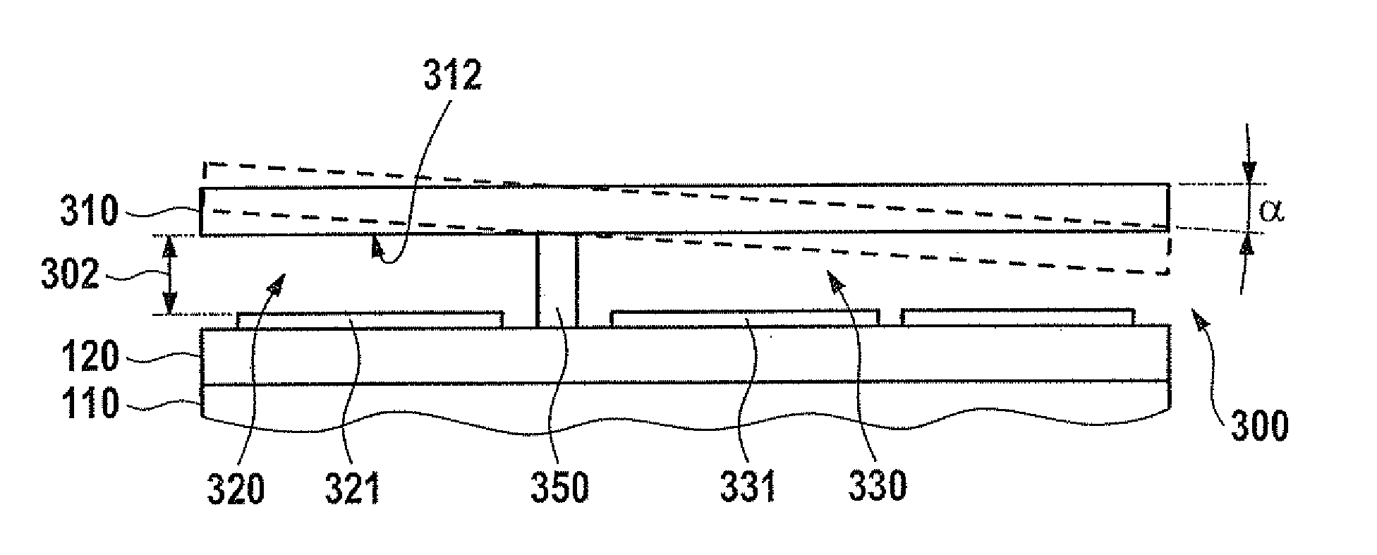
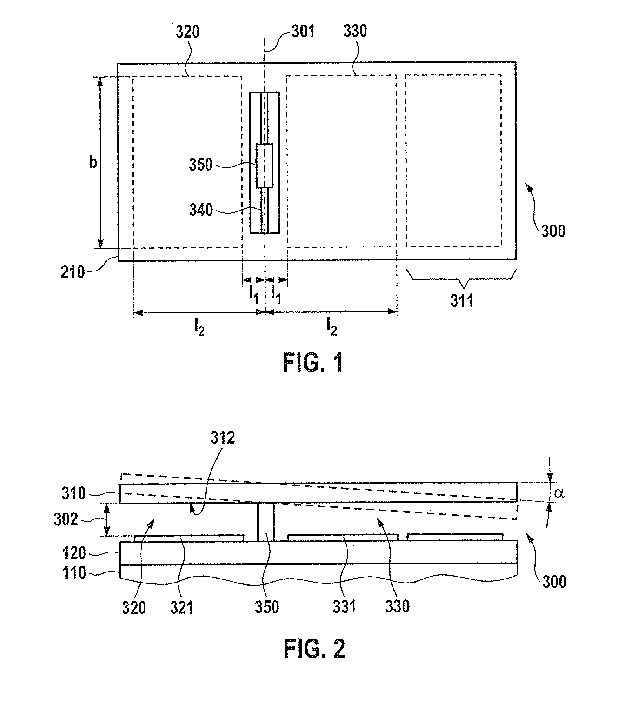
FIGS. 1 and 2 show a typical z-acceleration sensor (zES), which is designed in the so-called “rocker design.” Micromechanical sensor 300, which is shown in a top view in FIG. 1, generally includes a plate-shaped body 310, which, with the aid of a spring structure 340, is suspended rocker-like and deflectable in relation to a substrate 110 situated underneath. Plate 310, which is used as the seismic mass, may be connected via two torsion springs 340, for example, to a central carrier structure 350, the suspension of seismic mass 310 being selected in such a way that an auxiliary mass 311 results on one side, which causes a torque perpendicular to the substrate plane and therefore a deflection a of the rocker from its rest / zero position in the event of an acceleration of the sensor structure. The motion of rocker 310 is capacitively analyzed with the aid of two detection electrodes 321, 331, which are situated on both sides of carrier structure 350, and which each form a separate dete...


PUM

PropertyMeasurementUnit
thicknessaaaaaaaaaa
activation voltageaaaaaaaaaa
equilibrium deflectionaaaaaaaaaa

Abstract

A micromechanical component is described including a substrate having a spacer layer and a test structure for ascertaining the thickness of the spacer layer. The test structure includes a seismic mass, which is elastically deflectable along a measuring axis parallel to the substrate, a first electrode system and a second electrode system for deflecting the seismic mass along the measuring axis, having a mass electrode, which is produced by a part of the seismic mass, and a substrate electrode, which is situated on the substrate in each case, the first electrode system being designed to be thicker than the second electrode system by the layer thickness of the spacer layer.

Description

CROSS REFERENCEThe present application claims the benefit under 35 U.S.C. §119 of German Patent No. DE 102010029645.7 filed on Jun. 2, 2010, which is expressly incorporated herein by reference in entirety.FIELD OF THE INVENTIONThe present invention relates to a micromechanical component having a test structure for determining the layer thickness of a spacer layer in a micromechanically manufactured motion sensor. Furthermore, the present invention also relates to a method for manufacturing such a test structure.BACKGROUND INFORMATIONMicromechanical sensors are used in various technical applications, for example, as motion sensors for detecting the instantaneous acceleration or yaw rate. These motion sensors are frequently based on microelectromechanical systems (MEMS) which may be read out capacitively, in which the motion of a seismic mass is converted with the aid of a suitable electrode system into a measurable capacitance change. Corresponding electrodes may also be used for the...

Claims


Application Information

Patent Timeline
Patent Type & Authority Applications(United States)
IPC IPC(8): G01P15/125H05K3/00G01B7/06
CPCG01B7/085G01P2015/0831G01P2015/082G01P15/125B81B2201/0242Y10T29/49124B81C99/0045
Inventor REINMUTH, JOCHENBOESSENDOERFER, RALFFRANKE, AXELHATTASS, MIRKO
Owner ROBERT BOSCH GMBH
Why Eureka
Try Eureka