
Scene change detection apparatus

a technology for scene changes and detection apparatuses, applied in the field of scene change detection apparatuses, can solve problems such as brightness of input images, errors in determining scene changes, and problems of related art apparatuses

Inactive Publication Date: 2007-01-02
LG ELECTRONICS INC
View PDF3 Cites 71 Cited by
  • Summary
  • Abstract
  • Description
  • Claims
  • Application Information

AI Technical Summary

Benefits of technology

[0015]Accordingly, the present invention is directed to an apparatus for detecting a scene change that substantially obviates one or more problems due to limitations and disadvantages of the prior art.

Problems solved by technology

First, the related art apparatus may have problems when the brightness of the input images is instantaneously changed due to changes of illumination, a camera flash or other optical elements.
Accordingly, even though the scene change does not occur, a false alarm may occur due to an entire illumination change in the related art apparatus for detecting the scene change, thereby making mistakes of determining the scene change.

Method used


Image

  • Scene change detection apparatus
  • Scene change detection apparatus
  • Scene change detection apparatus

Examples


first embodiment

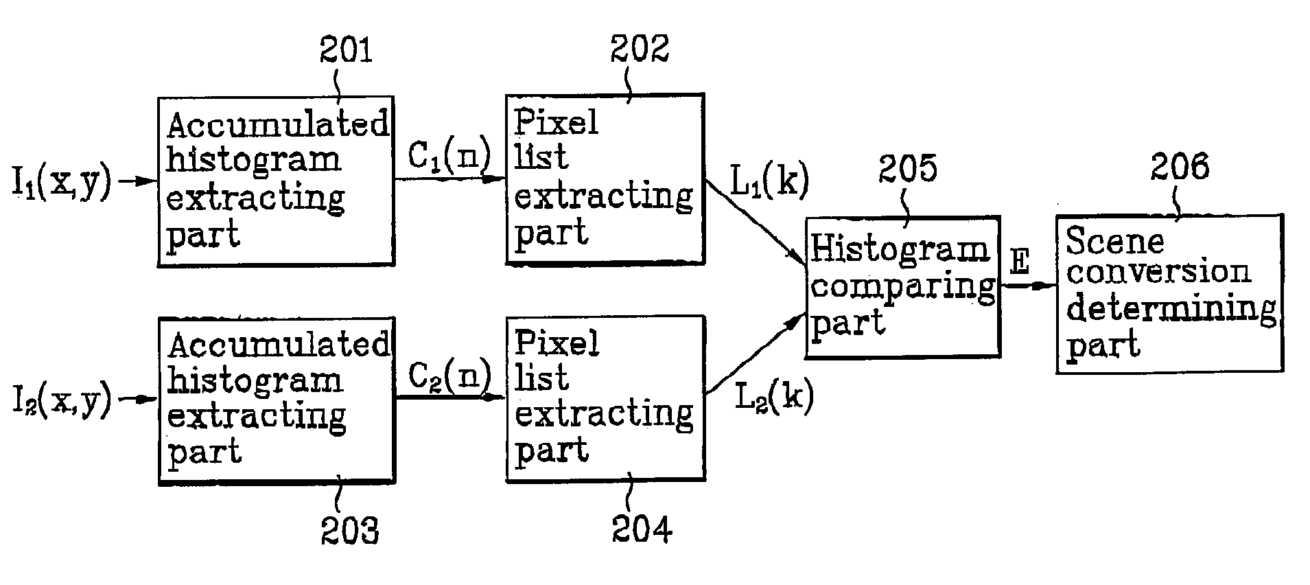
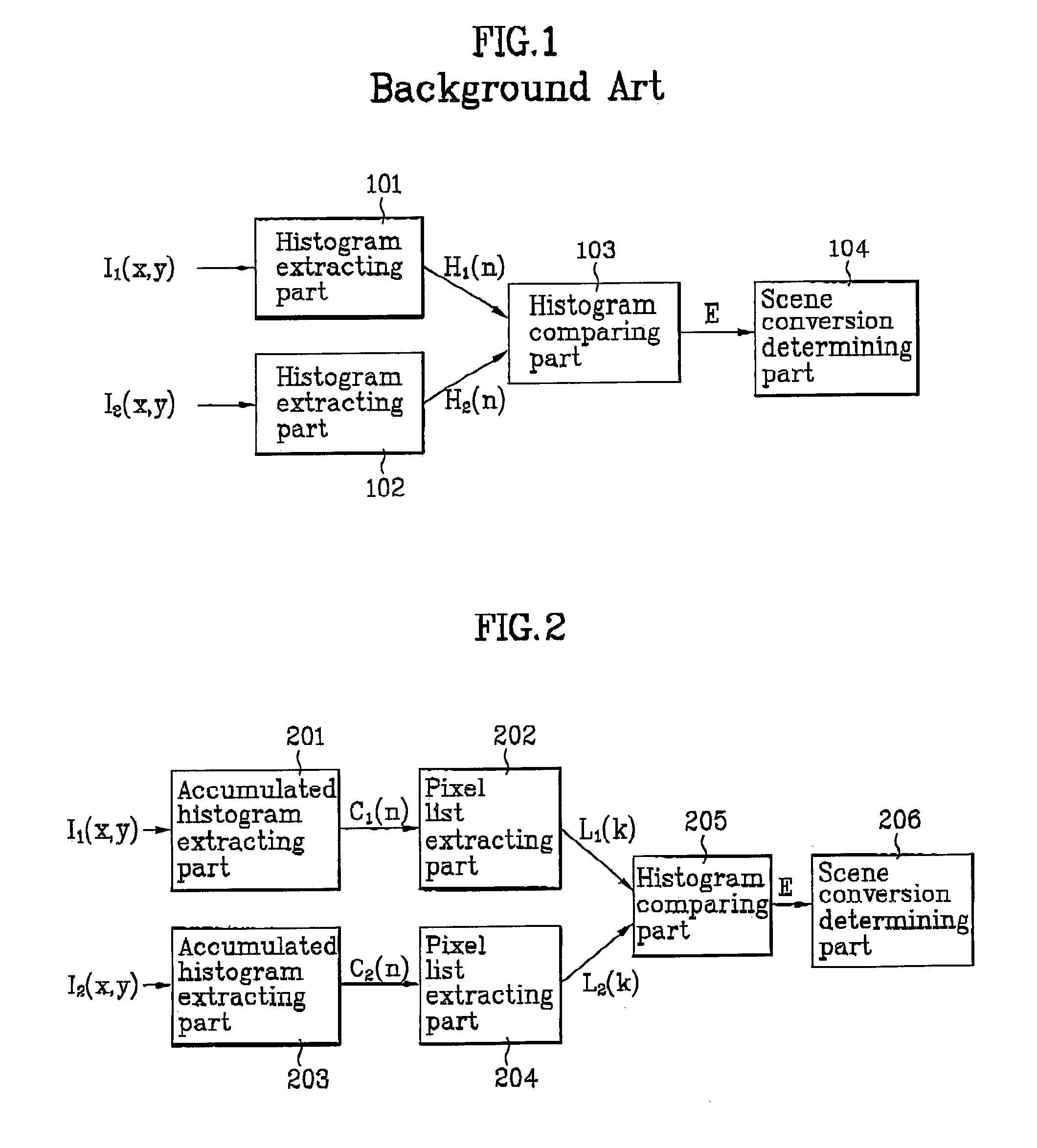
[0028]FIG. 2 is a block diagram illustrating an apparatus for detecting a scene change according to the present invention. Referring to FIG. 2, the apparatus for detecting the scene change includes a first accumulated histogram extracting part 201, a first pixel list exacting part 202, a second accumulated histogram extracting part 203, a second pixel list extracting part 294, a histogram comparing part 205 and a scene change determining part 206.

[0029]At this time, the first accumulated histogram extracting part 201 extracts an accumulated histogram of a first frame I1(x,y), and the first pixel list extracting part 202 extracts a pixel list corresponding to a specific accumulated distribution value from the first accumulated histogram extracting part 201. The second accumulated histogram extracting part 203 extracts an accumulated histogram of a second frame I2(x,y) being adjacent to the first frame I1(x,y), and the second pixel list extracting part 204 extracts a pixel list corres...

second embodiment

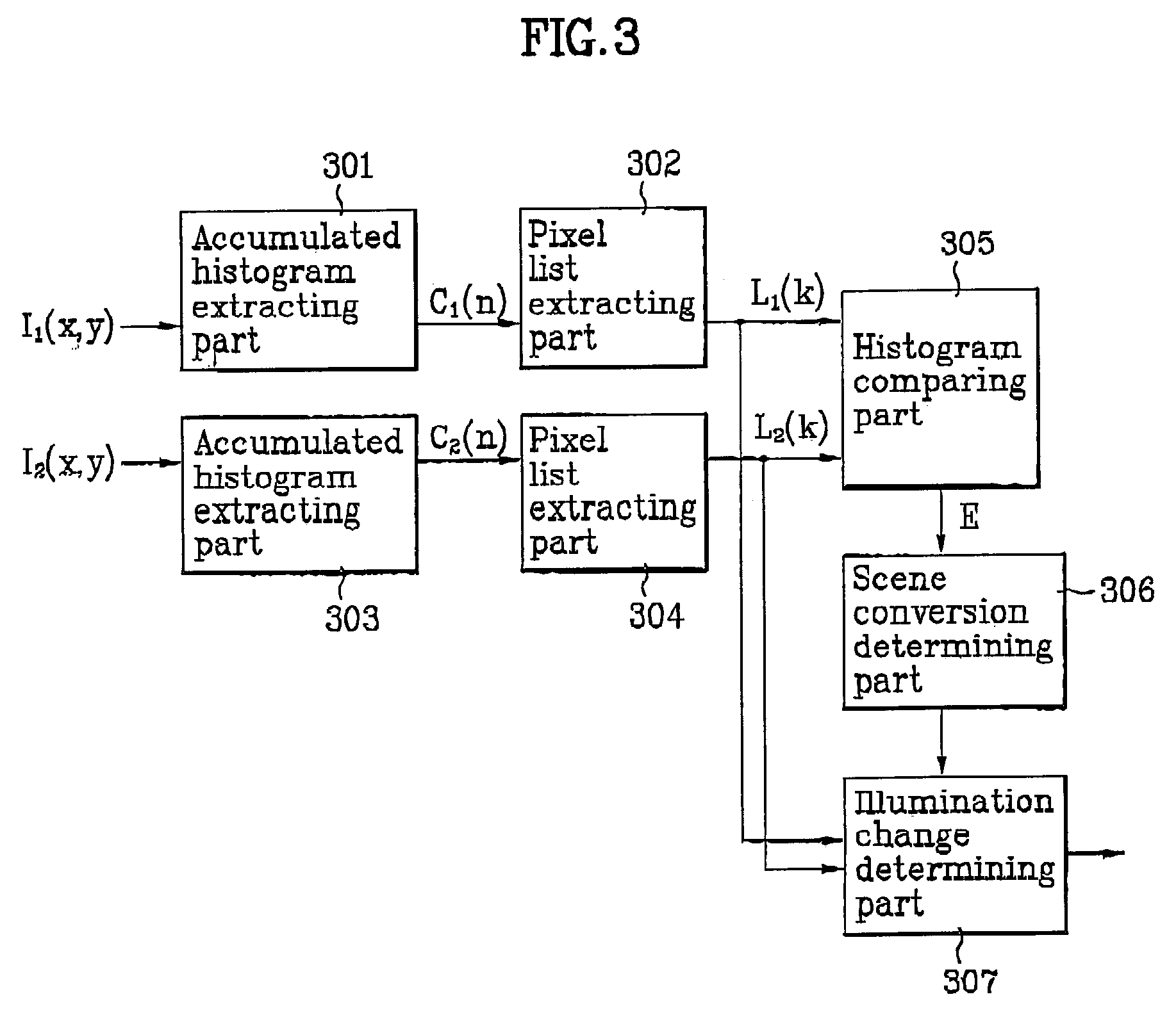
[0048]In the apparatus for detecting the scene change according to the present invention, if the scene change determining part 306 outputs “0”, it is determined that the scene change does not occur, so that a process step for the update to the frame difference register of the scene change determining part 306 is performed. Meanwhile, if the scene change determining pare 306 outputs “1”, the illumination change determining part 307 performs the aforementioned process steps repeatedly. At this time, if the illumination change deter g part 307 outputs “1”, it is also determined that the scene change does not occur, so that next frame is input, and then the aforementioned process steps are repeatedly performed. In this case, a process step for the update to the frame difference register of the scene change determining part 306 is not performed.

[0049]However, if the illumination change determining part 307 outputs “0”, it is determined that the scene change occurs, so that the process st...


PUM

PropertyMeasurementUnit
thresholdaaaaaaaaaa
frequencyaaaaaaaaaa
brightnessaaaaaaaaaa

Abstract

An apparatus for detecting a scene change is disclosed, which is provided for realizing functions such as a nonlinear browsing of a video, a video indexing and a key frame generation in a personal video recorder or video database. In the apparatus according to the present invention, accumulated histograms are extracted from the received two frames, and then a pixel value corresponding to a specific accumulated distribution of respective accumulated histograms is stored, thereby accurately detecting the scene change by comparing difference of pixel value lists. Also, an illumination change determining part for receiving first and second pixel lists from first and second pixel list extracting parts is additionally included so as to determine whether a brightness change of an image occurs due to a change of illumination conditions. Accordingly, it is possible to detect the scene change without any influence from changes of illumination, a camera flash or other optical elements.

Description

[0001]This application claims the benefit of Korean Application No. P2001-86096, filed on Dec. 27, 2001, which is hereby incorporated by reference as if fully set forth herein.BACKGROUND OF THE INVENTION[0002]Field of the Invention[0003]The present invention relates to an apparatus for detecting a scene change without any influence from an illumination change or a brightness change of an input image.[0004]Description of the Related Art[0005]In general, an apparatus for detecting a scene change is required to provide functions such as a nonlinear browsing of a video, video index and key fame generation in a personal video recorder and a video database.[0006]FIG. 1 shows one of methods for detecting a scene change, which is using a histogram. In the method shown in FIG. 1, the scene change is detected based upon a bin-to-bin difference method of comparing frequency difference of each bin of the histograms between two input images.[0007]FIG. 1 is a block diagram illustrating a related ...

Claims


Application Information

Patent Timeline
Patent Type & Authority Patents(United States)
IPC IPC(8): G06T7/00G06K9/00G06K9/62G06T5/40G11B27/28H04N5/14
CPCG06K9/00711H04N5/147G11B27/28G06V20/40G06T5/40
Inventor SUH, JONG YEUL
Owner LG ELECTRONICS INC
Learn More