Noise suppression apparatus

a noise suppression and noise technology, applied in the field of noise suppression apparatuses, can solve the problems of excessive noise suppression, noise suppression cannot be appropriately carried out, conventional apparatus, etc., and achieve the effect of reducing noise level, reducing noise, and reducing nois

Inactive Publication Date: 2007-01-02
MITSUBISHI ELECTRIC CORP
View PDF17 Cites 47 Cited by
  • Summary
  • Abstract
  • Description
  • Claims
  • Application Information

AI Technical Summary

Benefits of technology

[0023]It is an object of the present invention to solve the aforementioned problems, and to provide a noise suppression apparatus which can ...

Problems solved by technology

However, the conventional apparatus also has the following problems.
Because the grounds of the control are the estimated noise signal level and the estimated SNR, the no...

Method used


Image

  • Noise suppression apparatus
  • Noise suppression apparatus
  • Noise suppression apparatus

Examples


first embodiment

[0039]A noise suppression apparatus according to the present invention will be explained below, referring to the accompanied figures.

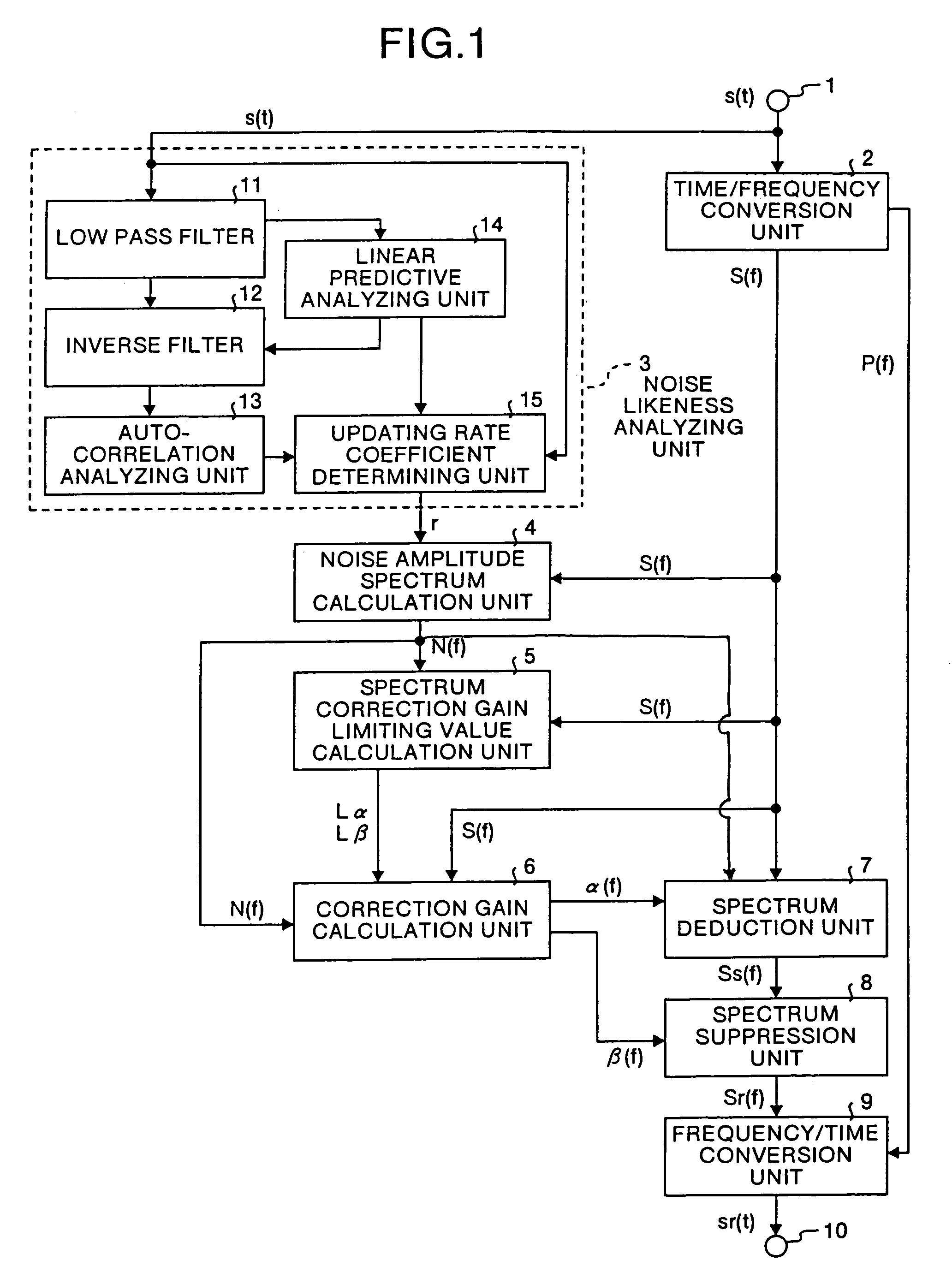
[0040]FIG. 1 is a block diagram showing the construction of the noise suppression apparatus according to the first embodiment of the present invention. The apparatus comprises input signal terminal 1, time / frequency conversion unit 2, noise likeness analyzing unit 3, noise amplitude spectrum calculation unit 4, spectrum correction gain limiting value calculation unit 5, correction gain calculation unit 6, spectrum deduction unit 7, spectrum suppression unit 8, frequency / time conversion unit 9 and an output signal terminal 10.

[0041]In this first embodiment, the spectrum correction gain limiting value calculation unit 5 and the correction gain calculation unit 6 constitute the spectrum correction gain calculation unit.

[0042]The principle of the function of the noise suppression apparatus of the present invention will be explained below with reference to ...

second embodiment

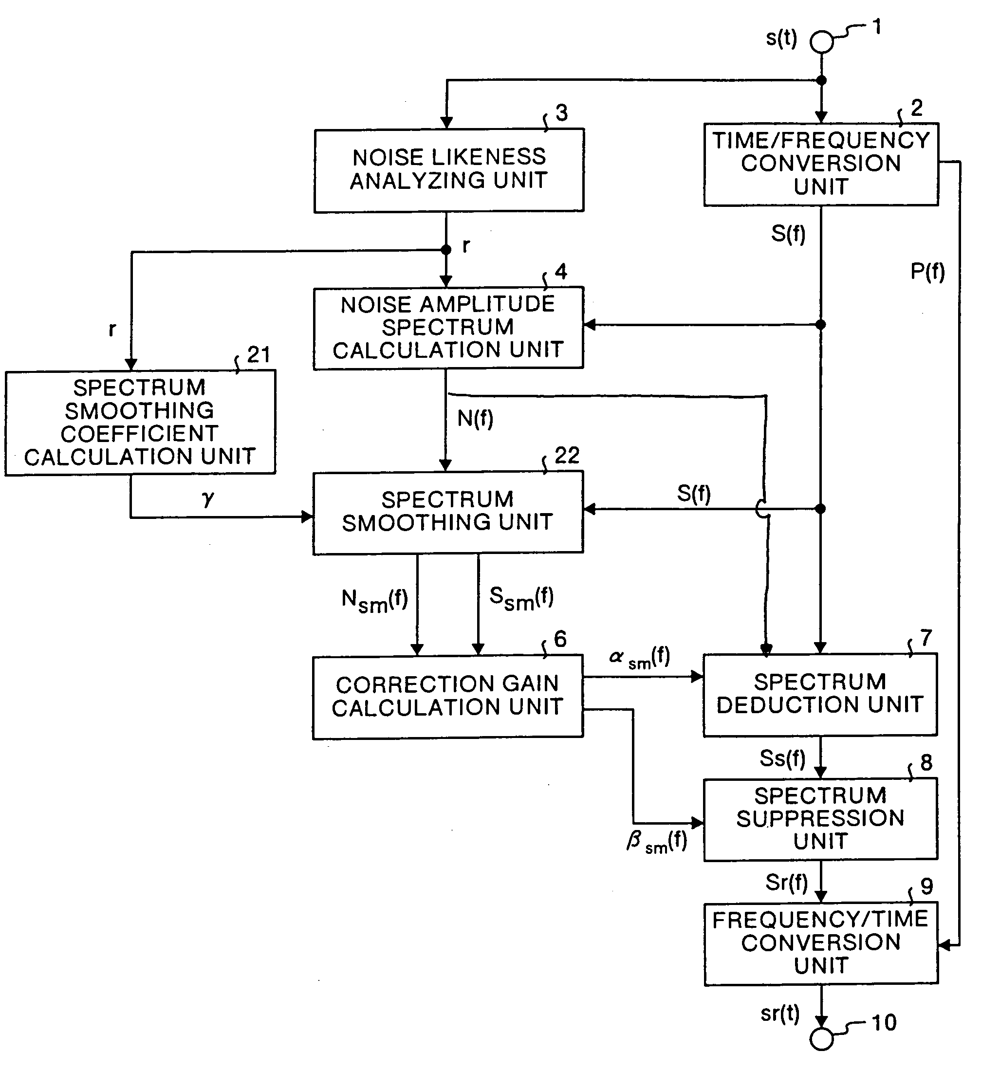
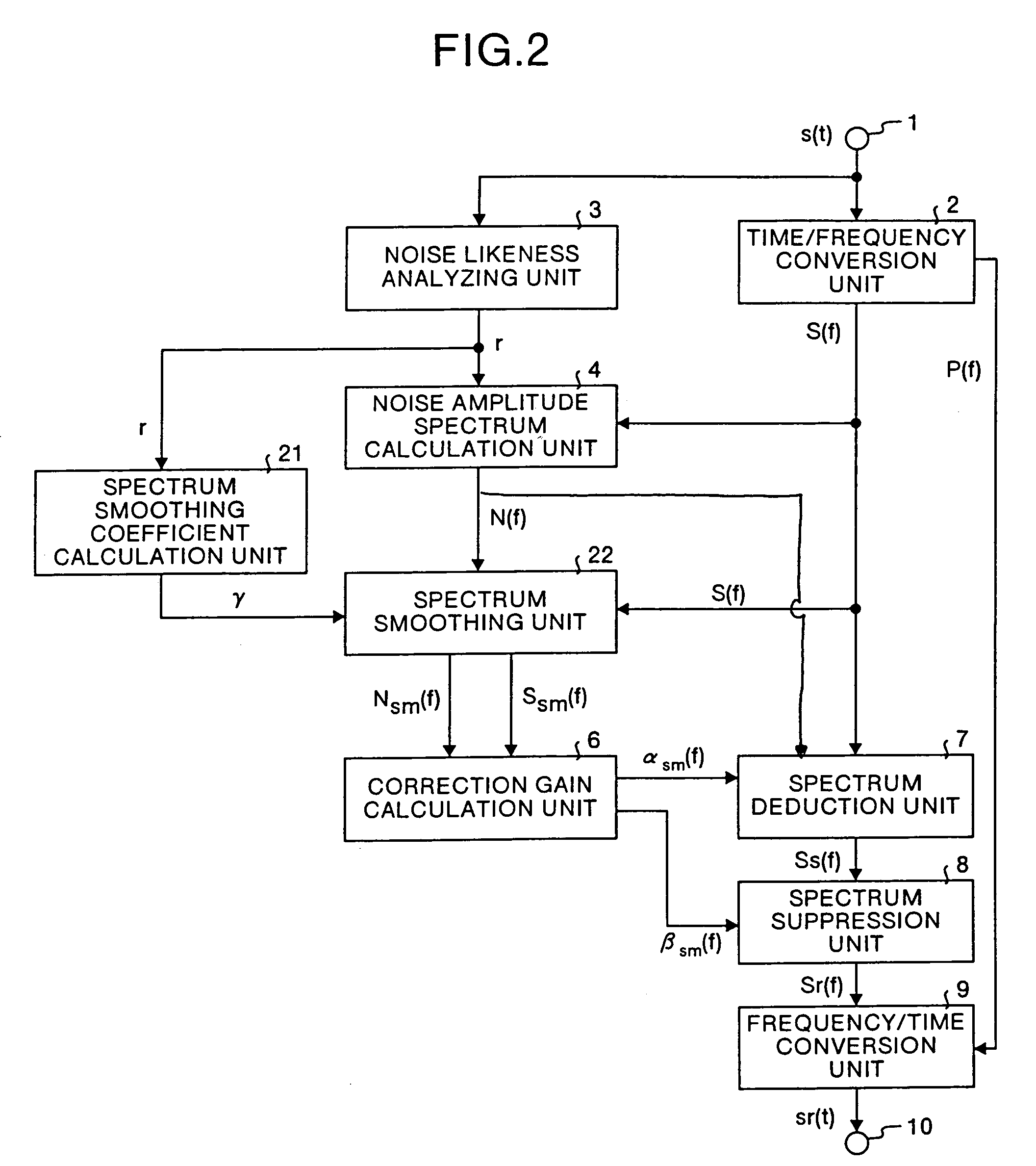
[0084]The noise suppression apparatus according to the present invention is explained below, referring to FIG. 2.

[0085]FIG. 2 is a block diagram showing the construction of the noise suppression apparatus according to the second embodiment. The construction of the apparatus differs from that shown in FIG. 1 in that the spectrum correction gain limiting value calculation unit 5 is removed, and newly a spectrum smoothing coefficient calculation unit 21 and a spectrum smoothing unit 22 are added. The other elements are identical to that in the apparatus of the first embodiment. Therefore, their explanation are omitted. The principle of the function of the second embodiment is explained below with reference to FIG. 2.

[0086]The spectrum smoothing coefficient calculation unit 21 calculates a time base spectrum smoothing coefficient γt for smoothing the spectrum in the time base, and a frequency base spectrum smoothing coefficient γf for smoothing the spectrum in a frequency base, correspo...

fourth embodiment

[0105]The spectrum smoothing coefficient corresponding to the state of the input sound can be calculated, for example, on the basis of the SNR of the present frame. FIG. 4 is a block diagram showing the construction of the

[0106]First, the spectrum smoothing coefficient calculation unit 21 obtains the SNR SNRfr of the input signal in the present frame, according to equation (18).

[0107]SNRfr⁡(ⅆB)=10⁢⁢log10⁢∑S⁡[f]⁢•S⁡[f]∑N⁡[f]⁢•N⁡[f](18)

[0108]Next, a temporal coefficient γt′ of the time base spectrum smoothing coefficient and a temporal coefficient γf′ of the frequency base spectrum smoothing coefficient are obtained, on the basis of the SNR SNRfr of the frame, according to equation (19). The time base spectrum smoothing coefficient is used for smoothing in the time base, and the frequency base spectrum smoothing coefficient is used for smoothing in the frequency base.

[0109]γi′={⁢0.9ifSNRfr>SNRthfr0.5else⁢⁢⁢γf′={⁢0.9ifSNRfr>SNRthfr0.5else(19)

[0110]Then, according to equation (20), AR s...


PUM


Abstract

In the noise suppression apparatus, a spectrum correction gain calculation unit calculates the noise amplitude spectrum correction gain and the noise removal spectrum correction gain using the input amplitude spectrum, noise amplitude spectrum and respective coefficients; a spectrum deduction unit deducts the product of the noise amplitude spectrum and the noise amplitude spectrum correction gain from the input amplitude spectrum and outputs the result as a first noise removal spectrum; a spectrum suppression unit multiplies the first noise removal spectrum by the noise removal spectrum correction gain and outputs the result as a second noise removal spectrum; finally a frequency/time conversion unit converts the second noise removal spectrum into a time domain signal.

Description

FIELD OF THE INVENTION[0001]The present invention relates to a noise suppression apparatus for use in a system, such as a voice communication system or a voice recognition system used in various noise circumstances, for suppressing noises, other than an object signal.BACKGROUND OF THE INVENTION[0002]A noise suppression apparatus for suppressing non-object signals, for example, noises superimposed on voice signals is disclosed, for example, in Japanese Patent Application Laid-Open (JP-A) No. 8-221093. The theoretical grounds of the apparatus disclosed therein is the so-called Spectral Subtraction Method (SS method), which focuses on the amplitude spectrum. This method is introduced in document 1 (Steven F. Boll, “Suppression of Acoustic noise in speech using spectral subtraction”, IEEE Trans. ASSP, Vol. ASSP-27, No. 2, April 1979).[0003]The conventional noise suppression apparatus disclosed in JP-A No. 8-221093 is explained below, referring to FIG. 13. In FIG. 13, reference numeral 1...

Claims


Application Information

Patent Timeline
IPC IPC(8): H04B15/00G10L15/20G10L15/00G10L15/02G10L17/00G10L19/02G10L21/0208G10L21/0232G10L25/00G10L25/78H03M7/30H04B1/10
CPCG10L21/0208
Inventor FURUTA, SATORU
Owner MITSUBISHI ELECTRIC CORP
Why Eureka
Try Eureka