
Self-service terminals

Inactive Publication Date: 2007-01-02
NCR CORP
View PDF14 Cites 5 Cited by
  • Summary
  • Abstract
  • Description
  • Claims
  • Application Information

AI Technical Summary

Benefits of technology

[0016]Preferably also, the display means includes a screen. The screen may be flat, or may take any suitable non-planar form; for example, by utilizing a mirrored concave screen it may be possible to produce real images in space. The screen may incorporate a keypad. Alternatively, or in addition, the screen may incorporate a touch sensitive surface. The function of individual keys or touch sensitive screen areas may be projected onto the screen and thus, operating in conjunction with processor means for controlling the terminal, the key functions may be varied as desired to suit a particular function, allowing greater flexibility in the operation of the terminal: for example in one mode keys may designate a natural sequence of numerals (0, 1, 2, 3 . . . 9), and in a subsequent mode may designate currency amounts (10, 20, 50, . . . 200), letters, symbols or cursor controls. The screen surface may also incorporate or encompass other functional elements, such as a card reader slot, a cash dispenser slot and receipt printer slot, and these elements may be highlighted at appropriate points during a transaction or operation, for example, by displaying an image of a hand pointing to the element or by differential lighting.
[0019]Conveniently, the image projecting means is located above a user location and projects images onto display means in front of the user location. Such image projecting means may be incorporated into a roof structure extending over the user location. Of course, the image projection means may be positioned at other locations relative to the user location and display means, and a plurality of projection locations may be provided to, for example, minimize the possibility of a user's hand or head casting a shadow over the display means. The image projection means may also project images onto the display means via one or more mirrors, lenses or other optical devices.

Problems solved by technology

The screen may be a CRT, which is generally relatively heavy and bulky, or an LCD panel, which is more compact but relatively expensive.
Further, to minimize expense and bulk, and also to accommodate the keypad and other user accessible features, such as a slot for a card reader, a cash dispense slot and a receipt printer slot, the screens tend to be relatively small, such that many users, particularly visually impaired users, may experience difficulties in using such machines.
Also, for security reasons, the screen will normally be covered by relatively thick glass, and this may introduce parallax problems for users of different heights when the screen displays preset functions to be selected by pressing one of the keys disposed to the sides of the screen in alignment with a respective function.

Method used


Image

  • Self-service terminals
  • Self-service terminals

Examples


Embodiment Construction

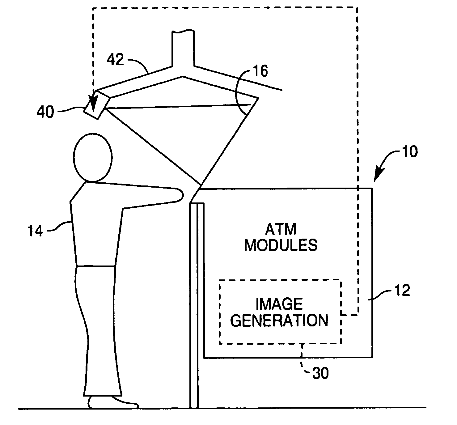
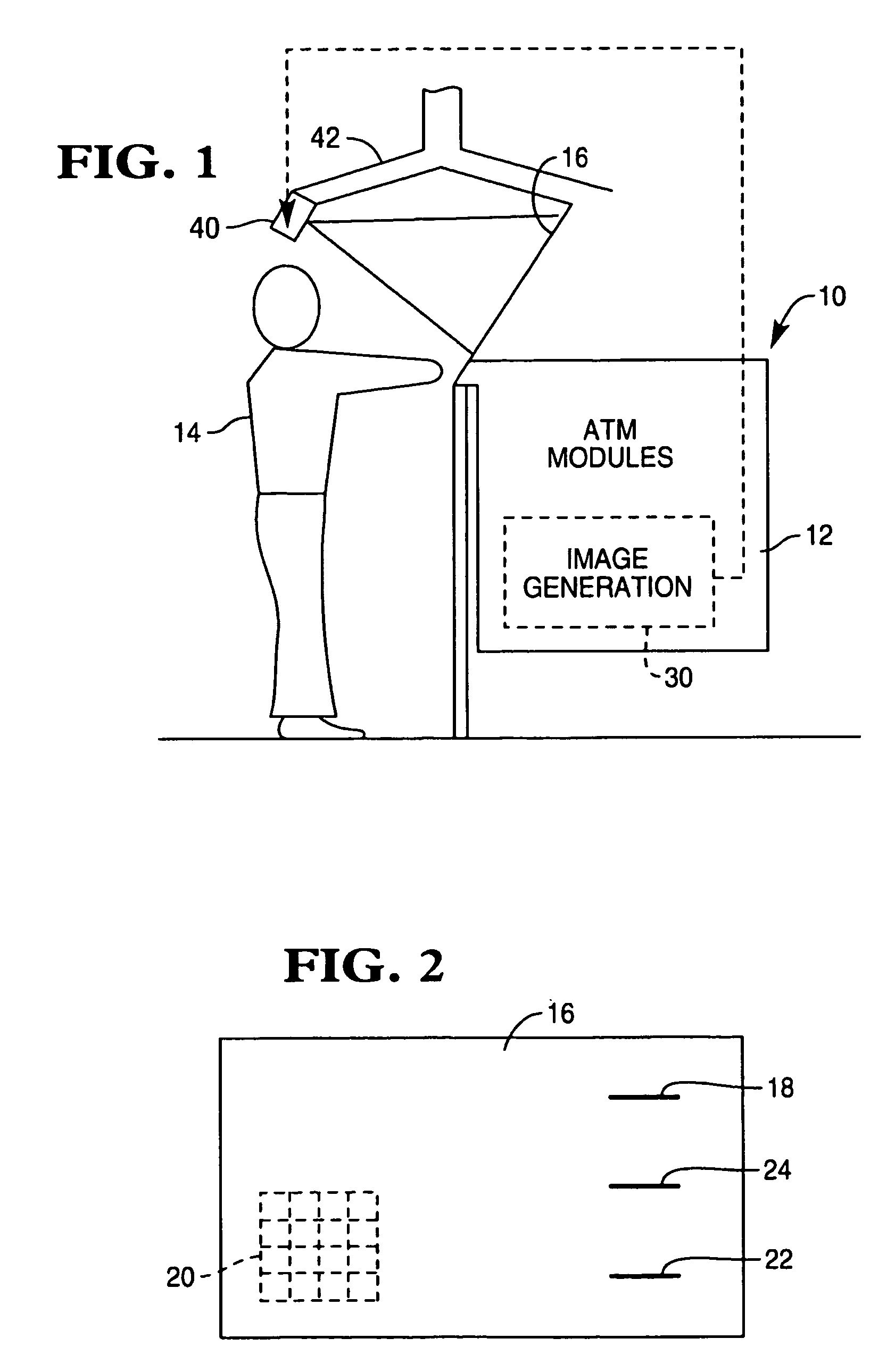
[0023]Reference is first made to FIG. 1 of the drawings, which illustrates an SST in accordance with one embodiment of the present invention, in the form of an ATM 10. The ATM 10 includes a collection of substantially conventional ATM modules 12, as are currently commercially available, however the manner in which the ATM 10 displays information and instructions for the user 14 differs from a conventional ATM, as described below.

[0024]Rather than the conventional interface means, comprising a user panel including, for example, a keypad and a relatively small CRT screen, the ATM 10 of this embodiment of the invention features a planar display screen 16 which incorporates all of the conventional user panel features within the screen 16. As may be seen from FIG. 2 of the drawings, the screen 16 incorporates a card reader slot 18, a keypad 20, a cash dispenser slot 22, and a receipt printer slot 24.

[0025]The image generation module 30 can be incorporated into the roof structure 42 exten...


PUM


Abstract

A self-service terminal (SST), such as an ATM includes apparatus for producing images containing instructions for users of the terminal, and an arrangement for projecting the images onto a screen forming part of a terminal user interface.

Description

BACKGROUND OF THE INVENTION[0001]This invention relates to a self-service terminal (SST), such as automated teller machine (ATM) and in particular to an SST provided with an improved display.[0002]Conventional self-service terminals (SSTs) such as automated teller machines (ATMs) interact with users via a user panel which conventionally includes a display screen, for displaying instructions, prompts and other outputs, and a keypad spaced from the screen and additional keys disposed to the sides of the screen for user inputs.[0003]The screen may be a CRT, which is generally relatively heavy and bulky, or an LCD panel, which is more compact but relatively expensive. Further, to minimize expense and bulk, and also to accommodate the keypad and other user accessible features, such as a slot for a card reader, a cash dispense slot and a receipt printer slot, the screens tend to be relatively small, such that many users, particularly visually impaired users, may experience difficulties in...

Claims


Application Information

Patent Timeline
IPC IPC(8): G06Q40/00G06Q20/10G07F19/00
CPCG06Q20/1085G07F19/205G07F19/201G07F19/20
Inventor GROSSI, MARK M.PATON, GRANT C.NICOLL, KENNETH A.
Owner NCR CORP
Learn More