Capacitive load cell apparatus having silicone-impregnated foam dielectric pads

a technology of dielectric pads and capacitive load cells, which is applied in the direction of fixed capacitor details, instruments, force/torque/work measurement apparatus, etc., can solve the problems of reducing accuracy and repeatability of load measurement, and undesirable variable dielectric constants, so as to reduce separation and minimize humidity-related variability

Inactive Publication Date: 2007-01-09
DELPHI TECH INC
View PDF17 Cites 23 Cited by
  • Summary
  • Abstract
  • Description
  • Claims
  • Application Information

AI Technical Summary

Problems solved by technology

The variability of the dielectric constant is clearly undesirable because it degrades accuracy and repeatability of the load measurement.

Method used


Image

  • Capacitive load cell apparatus having silicone-impregnated foam dielectric pads
  • Capacitive load cell apparatus having silicone-impregnated foam dielectric pads
  • Capacitive load cell apparatus having silicone-impregnated foam dielectric pads

Examples


Embodiment Construction

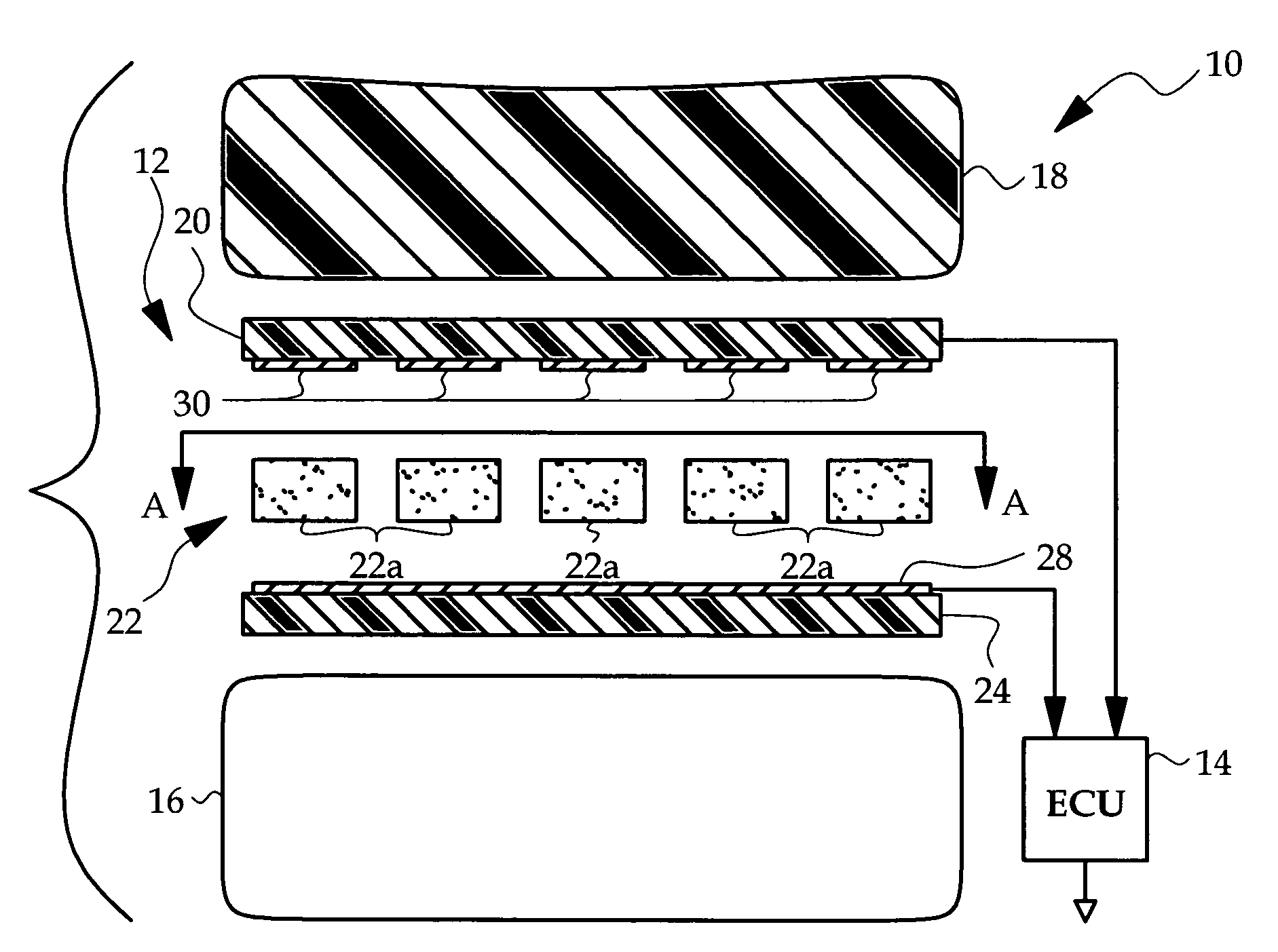
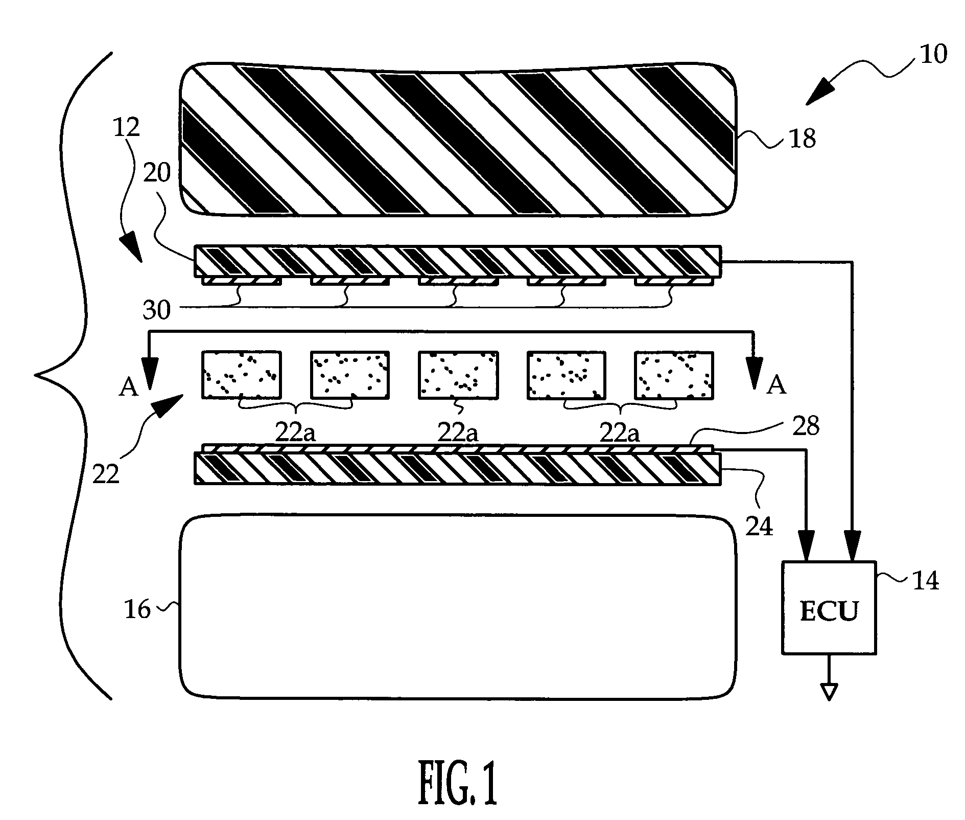
[0008]While the capacitive load cell apparatus of the present invention may be used in various applications, it is disclosed herein in the context of an apparatus for detecting the weight and / or distribution of weight applied to a vehicle seat. In general, a capacitive load cell comprises upper and lower conductor plates separated by a compressible non-conductive dielectric, such that mechanical loading of the cell reduces the separation distance of the conductor plates, increasing the electrical capacitance between the upper and lower plates. As applied to a vehicle seat, the capacitive load cell is preferably disposed between the frame and bottom cushion of the seat as depicted herein, but it will be understood that the load cell may be installed in a different location such as in the bottom cushion, in or behind a back cushion, and so on.

[0009]Referring to FIG. 1, the reference numeral 10 generally designates a seat bottom and sensor apparatus according to this invention. The sen...


PUM


Abstract

A capacitive load cell includes upper and lower capacitor plates and an intermediate array of dielectric pads formed of silicone-impregnated open-cell urethane foam (i.e., gel pads). The silicone essentially displaces air that would otherwise be trapped in the foam, contributing to a dielectric having minimal humidity-related variability. The upper capacitor plate is defined by an array of individual charge plates, the lower capacitor plate defines a ground plane conductor common to each of the charge plates, and the dielectric pads are disposed between the ground plane conductor and each of the charge plates, leaving channels between adjacent dielectric pads. When occupant weight is applied to the seat, the dielectric pads transmitting the weight distend laterally into the channels to reduce the separation between the respective upper and lower capacitor plates, and the consequent change in capacitance is detected as a measure of the applied force and the force distribution.

Description

TECHNICAL FIELD[0001]The present invention relates to a capacitive load cell for estimating occupant weight applied to a vehicle seat, and more particularly to a load cell having a dielectric material that minimizes humidity-related error.BACKGROUND OF THE INVENTION[0002]Various sensing technologies have been utilized to classify the occupant of a vehicle seat for purposes of determining whether to enable or disable air bag deployment, and / or for purposes of determining how forcefully an air bag should be deployed. The present invention is directed to an approach in which at least one capacitive load cell is installed in a vehicle seat, and the capacitance of the load cell is measured to provide an indication of the weight applied to the seat and / or the distribution of the applied weight. In general, a capacitive load cell includes at least first and second conductive plates separated by a compressible dielectric such as a sheet of rubber or urethane foam. For example, representativ...

Claims


Application Information

Patent Timeline
Patent Type & Authority Patents(United States)
IPC IPC(8): G01B7/16
CPCG01G19/4142G01G7/06
Inventor FORTUNE, DUANE D.SANFTLEBEN, HENRY M.
Owner DELPHI TECH INC
Why Eureka
Try Eureka