

Joint arrangement for a gear shift mechanism
- Summary
- Abstract
- Description
- Claims
- Application Information
AI Technical Summary
Benefits of technology
Problems solved by technology
Method used
Image

Examples
Embodiment Construction
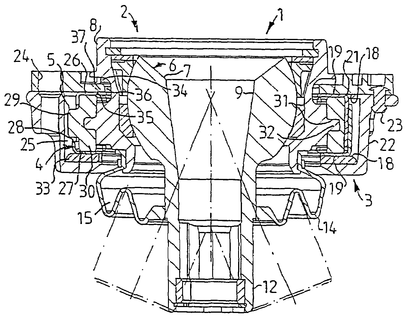
[0018]FIG. 1 shows a sectional view of a joint arrangement 1′ according to the prior art, comprising a coupling element 2′ and a mounting element 3′ as well as a damping element 4′ arranged between the coupling element 2′ and the mounting element 3′. The damping element 4′ consists of an annular rubber element 5′, which is joined to the couping element 2′ and to the mounting element 3′, so that the coupling element 2′ can be displaced in all directions relative to the mounting element 3′. In the known joint arrangement 1′, the coupling element 2′ is a ball and socket joint 6′, comprising a ball 7′ and a bearing housing 8′ at least partially surrounding the ball 7′. The ball 7′ is provided with a hollowed out portion 9′ which is disposed to receive one end of a gear shift lever (not shown in FIG. 1). A pin 12′ is arranged at the lower portion of the ball 7′. The pin 12′ is coupled to a link mechanism (not shown) which transmits movement from the shift lever to the vehicle gearbox. Th...
PUM
 Abstract
Description
Claims
Application Information