Mooring of a floating unit to a vessel side

a floating unit and mooring technology, applied in the field of floating units, can solve the problems of large force and load, difficult to secure and fix the floatable unit in relation to the vessel, and difficulty in entering the floatable unit from the vessel

Inactive Publication Date: 2007-01-09
VIKING LIFE SAVING EQUIP
View PDF12 Cites 7 Cited by
  • Summary
  • Abstract
  • Description
  • Claims
  • Application Information

AI Technical Summary

Benefits of technology

[0017]An object of the present invention is to wholly or partially overcome the above disadvantages of the prior art. More specifically, it is an object to provide a floatable unit, which can be securely positioned alongside a vessel during evacuation of passengers or crew members.

Problems solved by technology

These movements of the vessel, as well as of the floatable unit are causing the difficulties of entering the floatable unit from the vessel, as the distance, both in height, in the transverse as well as in the longitudinal, direction between the vessel and the floatable unit is varying constantly, whereby it is almost impossible to hold the floatable unit in a secure and fixed position in relation to the vessel.
Often the evacuation of the persons from the vessel takes place during heavy weather, which furthermore influences as well as exerts great forces and loads on the vessel and the floatable unit.
However, in the cases where the distance between the deck of the vessel and the floatable unit is limited, a shorter chute might be used.
In this case, the longitudinal displacement of the raft in relation to the vessel, will cause the chute to be inclined to such an extent that the chute becomes occasionally unusable.
However, similar drawbacks and disadvantages occur in relation to the transverse and longitudinal distances between the evacuation point of the vessel and the floatable unit.
The known mooring systems have the disadvantage that when the liferafts shall be pulled into the vessel side to evacuate passengers down in the raft great pulling forces have to be used, which affect the area where the lines are fixed.
Whereby the raft is easily destroyed in the area around the fixed point for the mooring lines.

Method used


Image

  • Mooring of a floating unit to a vessel side
  • Mooring of a floating unit to a vessel side
  • Mooring of a floating unit to a vessel side

Examples


Embodiment Construction

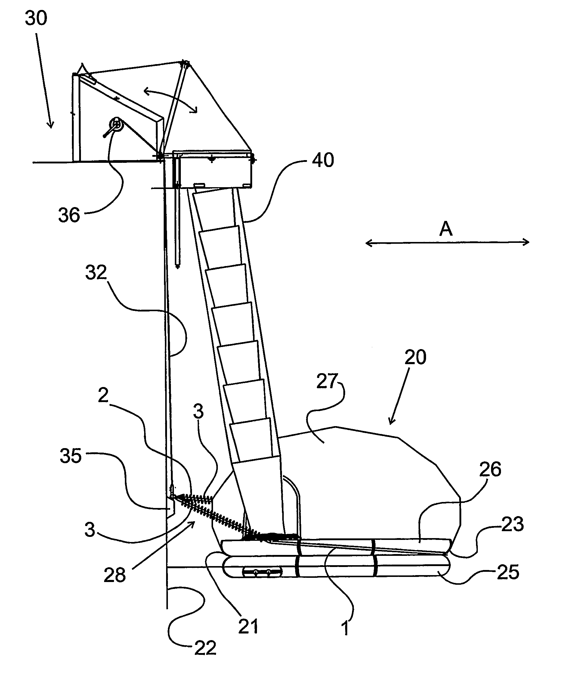
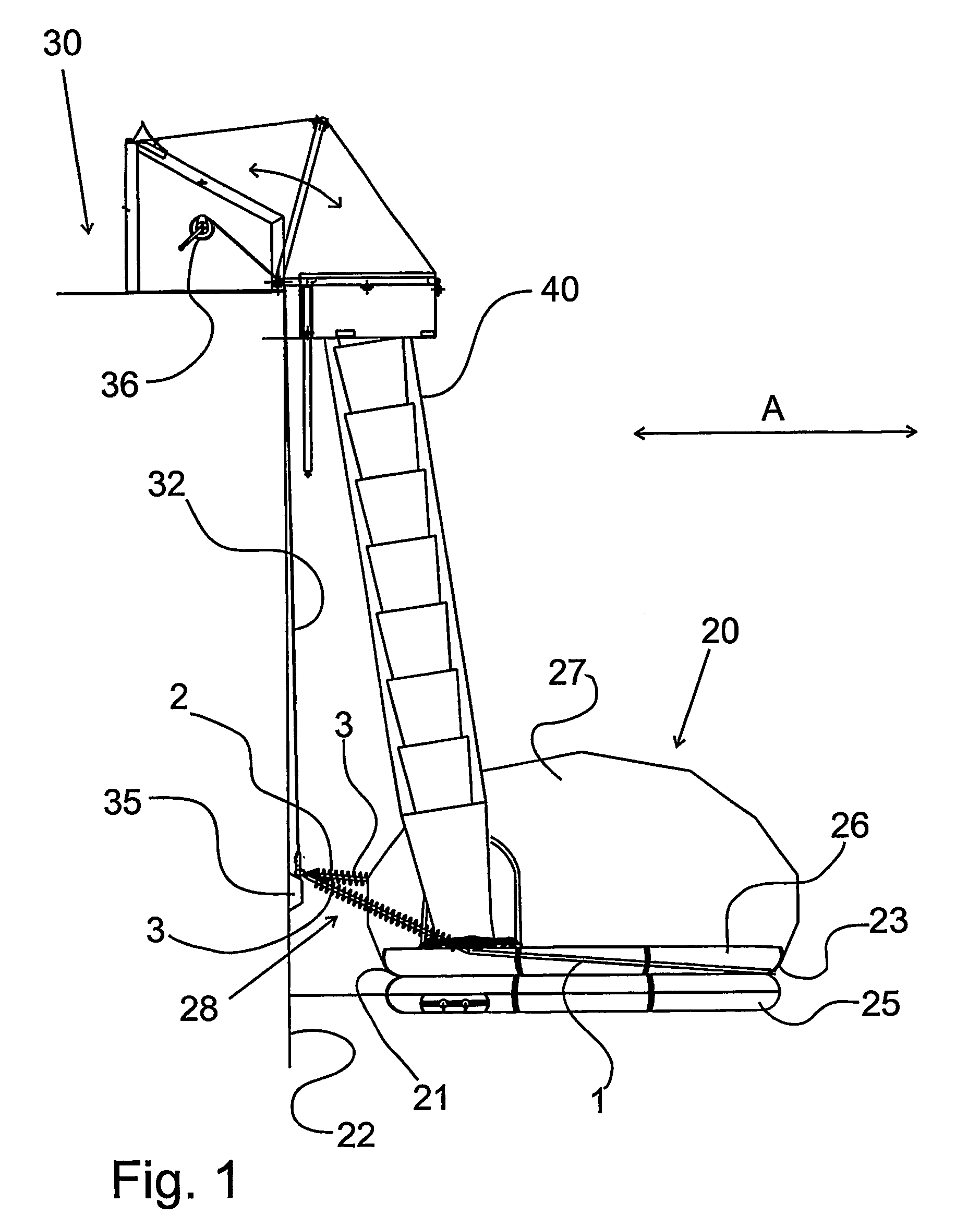
[0053]In the shown example the evacuation of the passengers or crew members takes place from the vessel by means of a chute, the evacuation from the vessel into the raft is independent of the mooring system, and may thus take place by means of a slide, a rope, ladders, jumps or in other ways.

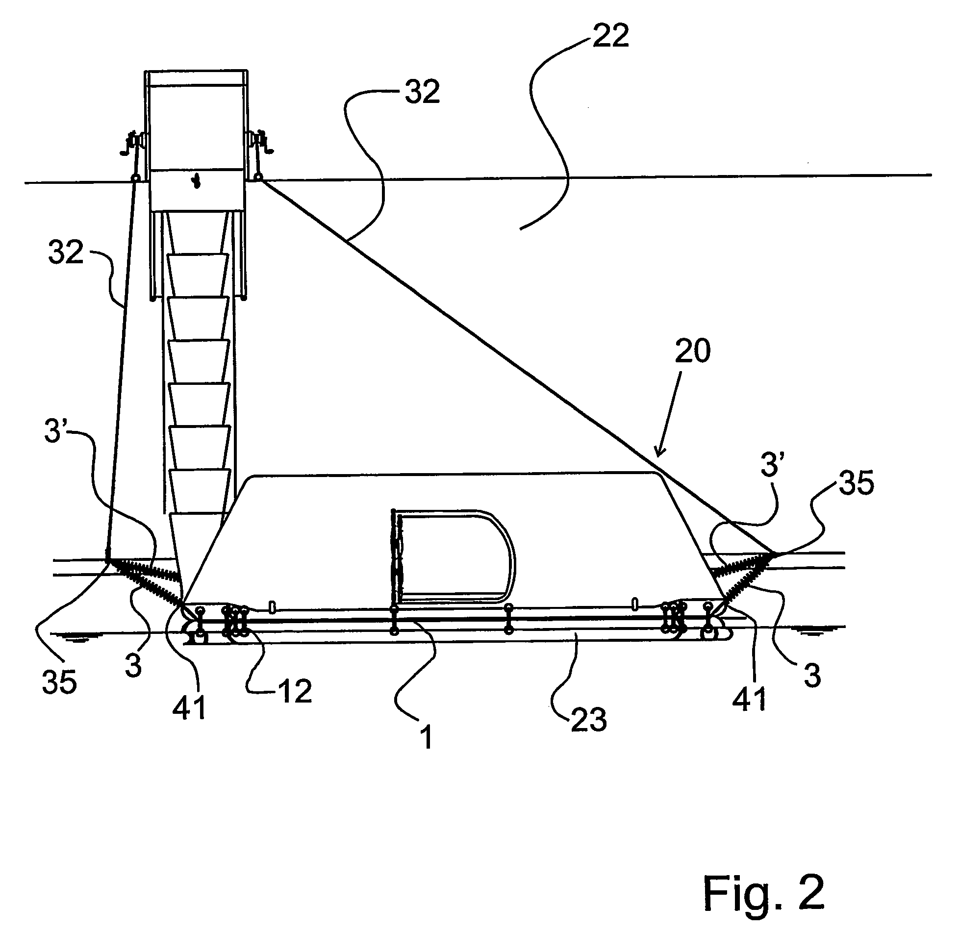
[0054]The mooring system will be described in an embodiment, which in no way shall be considered as limiting for the invention.

[0055]In FIG. 1 the floatable unit 20 is shown, here in the form of an inflatable liferaft. According to the invention the floatable unit may also be a platform or a MOB-boat (man over board).

[0056]The floatable unit 20 has a first side 21 facing a vessel side 22 and a second side 23 facing away from the vessel side 22. The inflatable floatable unit 20 furthermore comprises a peripheral edge having two inflatable chambers 25, 26 surrounding a bottom (not shown) secured in leak tight fashion to the tubular inflatable chambers. The floating unit 20 also comprises a canopy ...


PUM


Abstract

A mooring system (28) of a floatable unit (20), such as life raft or platform, the floatable unit (20) having a first side (21) facing a vessel side (22) and a second side (23) facing away from the vessel side (22). The mooring system (28) comprises at least two back springs (2) which are in connection with the first side (21) of the floatable unit (20), and at least one strap (1) which is in connection with the second side (23) of the floatable unit (20), the back springs (2) and the strap (1) being connected to the vessel (30). The back springs (2) are adapted to control the floatable unit (20) in a longitudinal direction in relation to the vessel (30), and the strap (1) is adapted to control the floatable unit (20) in a transverse direction in relation to the vessel (30). The floatable unit is held in secure and fixed position alongside the vessel side, thereby enabling people evacuating from the vessel to enter the floatable unit without any high risk of injury or damage.

Description

[0001]This is a 35 U.S.C. 371 application of PCT / DK02 / 00678, filed on Oct. 9, 2002, which claims the benefit of priority to Danish Application No. PA 2002-00498 filed Apr. 4, 2002, each of which being incorporated by reference herein.FIELD OF THE INVENTION[0002]The present invention relates to a floatable unit, such as liferaft or platform, having a first side facing a vessel side and a second side facing away from the vessel side, said floatable unit comprising a mooring system.[0003]The invention also relates to a mooring system for floatable units.[0004]The term vessel is in this context to be construed as being a marine installation, such as vessel, ship, boat or offshore installation.BACKGROUND ART[0005]Floatable units, such as liferafts or platforms are often used in the evacuation of the passengers or crew members from a vessel.[0006]Heeling movements as well as the movements which are caused by the loads such as wind, current or waves, exerted on the vessel render that the p...

Claims


Application Information

Patent Timeline
Patent Type & Authority Patents(United States)
IPC IPC(8): B63C9/22A62B1/20B63B21/00B63B35/34B63C9/02
CPCB63B21/00B63B35/34B63C9/02B63B2021/203B63B2021/005
Inventor NIELSEN, PETER BRINCH
Owner VIKING LIFE SAVING EQUIP
Why Eureka
Try Eureka