Unlock instant, AI-driven research and patent intelligence for your innovation.

Method to install a cylindrical pipe in a wellbore

a technology of cylindrical pipes and wellbores, which is applied in the direction of pipe elements, fluid removal, mechanical equipment, etc., can solve the problems of irregular pipe sections, deformation of the internal pressure performance of the reformed or deployed cylindrical pipes, and the retention of fold marks, so as to improve the external pressure resistance of the cylindrical pipes, improve the circularity of the section, and improve the effect of the external pressure resistan

Inactive Publication Date: 2007-01-09
NOBILEAU PHILIPPE
View PDF15 Cites 21 Cited by
  • Summary
  • Abstract
  • Description
  • Claims
  • Application Information

AI Technical Summary

Benefits of technology

"The invention provides a method and system for installing a cylindrical pipe downhole without limitations of previous methods, regardless of the technique used to get them through the well. The method involves folding and unfolding the pipe or using a small pipe that is heavily expanded, which improves the external pressure resistance of the pipe. The method can be used in any portion of pipe that must temporarily pass through a restriction or opening of smaller size during the running to the target depth and must take again by plastic deformation a final cylindrical shape larger than the dimensions of the opening. The expansion mandrel is moved by applying a pressure on the back of it with the sealing device to the cylindrical pipe to be expanded being located on the small diameter of the conical portion of the expansion mandrel."

Problems solved by technology

Unfortunately due to the existence of an elastic phase in the stain-stress curve of metallic material the final second shape spring back after the expander / gauge move out and exhibit marks on the wall where the horseshoe shape folds were.
The direct consequence is that the misshapen shape restricts the access and degrades the external pressure performance of the reformed or deployed cylindrical pipe.
But these methods result either in an irregular section of the pipe, which keeps the fold marks made during folding, in the case the section was initially folded, or in a thickness limitation, in the case where the pipe is initially cylindrical and is simply expanded.

Method used


Image

  • Method to install a cylindrical pipe in a wellbore
  • Method to install a cylindrical pipe in a wellbore
  • Method to install a cylindrical pipe in a wellbore

Examples


second embodiment

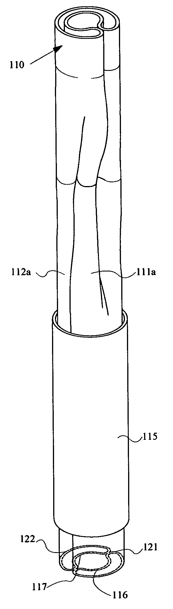
[0041]In the invention, a downhole equipment 110 (FIG. 7) comprising sections of pipe 111a and 111b is crushed with its sections of pipe folded up to allow its descent in the reduced passage of well casing 115. An example of such equipment is described in the U.S. Pat. Nos. 5,979,560 and 6,253,852.

first embodiment

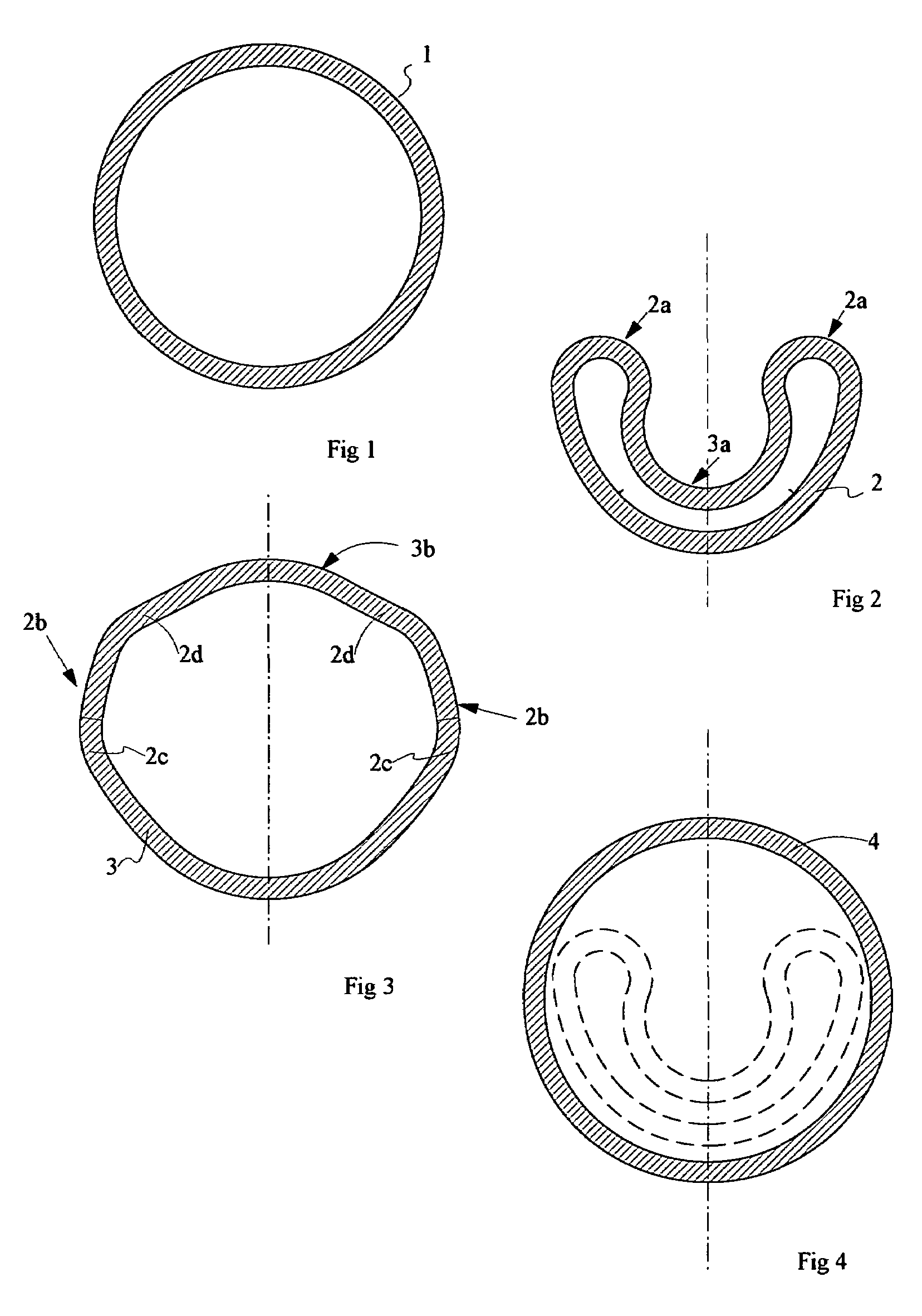
[0042]When this equipment reaches the target depth which features a widened cavity (not shown), the equipment is re-inflated (FIG. 8) by pumping fluid which will give it a general cylindrical shape 120. But as previously said, this re-inflated shape exhibits on the straight parts of the pipes 111b and 112b of the equipment, some variations of radius localized at the previous fold location (see FIG. 3) and it is necessary to eliminate them to improve the external pressure resistance of these sections. This is carried out by a mechanical action of slight expansion mandrel (FIG. 5) such as previously described for the first embodiment which is run on drillpipe through the equipment and which enters successively the two branches 111b and 112b to carry out a slight expansion of the pipes constituting those branches.

[0043]In the case of downhole equipment 110, which comprises two branches 111 and 112, it is advantageous to fold them with a fold on each pipe 116 and 117 facing one another ...


PUM


Abstract

A method to install a cylindrical pipe in a wellbore through a previously installed casing forming a reduced opening by running a pipe within the casing, the pipe having a first shape having dimensions smaller than the dimensions of the reduced opening; then deforming the pipe to convert the pipe from the first shape to a substantially cylindrical second shape in a cavity having larger dimensions than both the reduced opening and the second shape, and last displacing an expansion mandrel having a circular section to expand, in the plastic range, the pipe having a substantially cylindrical second shape to a cylindrical third shape.

Description

TECHNICAL FIELD[0001]This invention relates to cylindrical pipes in oil wells and in particular, a method and associated system to install a cylindrical pipe into a well through a previously installed casing forming a reduced opening, the pipe having a first shape having dimensions smaller than the dimensions of the reduced opening and then deploying adequately the cylindrical pipe in a cavity located below the previously installed casing.BACKGROUND ART[0002]Oil and gas wells are typically drilled by installing a conductor pipe to a first depth, then drilling the well to a second depth. Usually, a string of casing is made up by coupling together sections of pipe, each being about forty feet long, and lowering the string through the conductor pipe to the second depth. Cement is then pumped down the casing, which flows back up the annulus between the casing and the open borehole. Drilling is resumed to a third depth and the process is repeated with another smaller diameter nested casi...

Claims


Application Information

Patent Timeline
Patent Type & Authority Patents(United States)
IPC IPC(8): E21B23/02E21B17/08E21B17/14E21B33/12E21B33/14E21B41/00E21B43/10F16L55/165
CPCE21B17/08E21B17/14E21B33/1212F16L55/1657E21B41/0042E21B43/103E21B43/105E21B33/14
Inventor NOBILEAU, PHILIPPE
Owner NOBILEAU PHILIPPE
Features
  • R&D
  • Intellectual Property
  • Life Sciences
  • Materials
  • Tech Scout
  • Unparalleled Data Quality
  • Higher Quality Content
  • 60% Fewer Hallucinations
Learn More