

Silencer
Inactive Publication Date: 2007-01-09
SILENTOR HLDG AS
View PDF28 Cites 11 Cited by
- Summary
- Abstract
- Description
- Claims
- Application Information
AI Technical Summary
Benefits of technology
[0004]The aim of the present invention is to design silencer flow elements which may replace simple perforated pipe elements in silencers retaining or even improving the beneficial flow distribution and acoustic resistance effects, but with smaller pressure energy losses, preferably with no or only slightly increased cost of manufacture and with no or only minor increase of silencer weight.
[0006]The silencer according to the invention incorporates flow distributing means. When such flow distributing means are incorporated in a prior art silencer, they may result in lower pressure-drop across the silencer. At the same time, the silencing performance of the silencer may be substantially retained or even improved.
Problems solved by technology
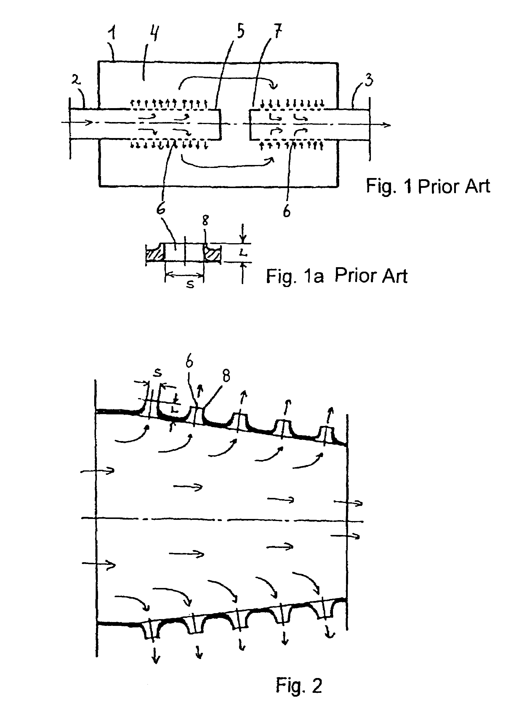
Such perforations are normally made as simple holes and create pressure energy losses affecting engine performance adversely.
Method used
View moreImage
Smart ImageViewing Examples

Examples
first embodiment
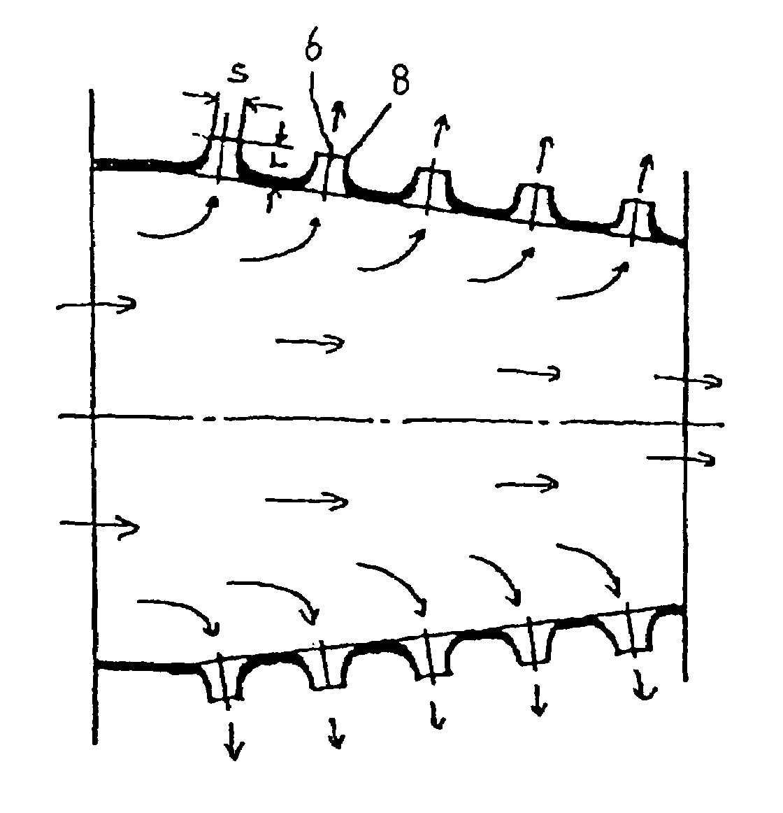
[0010]FIG. 2 shows the invention.
second embodiment
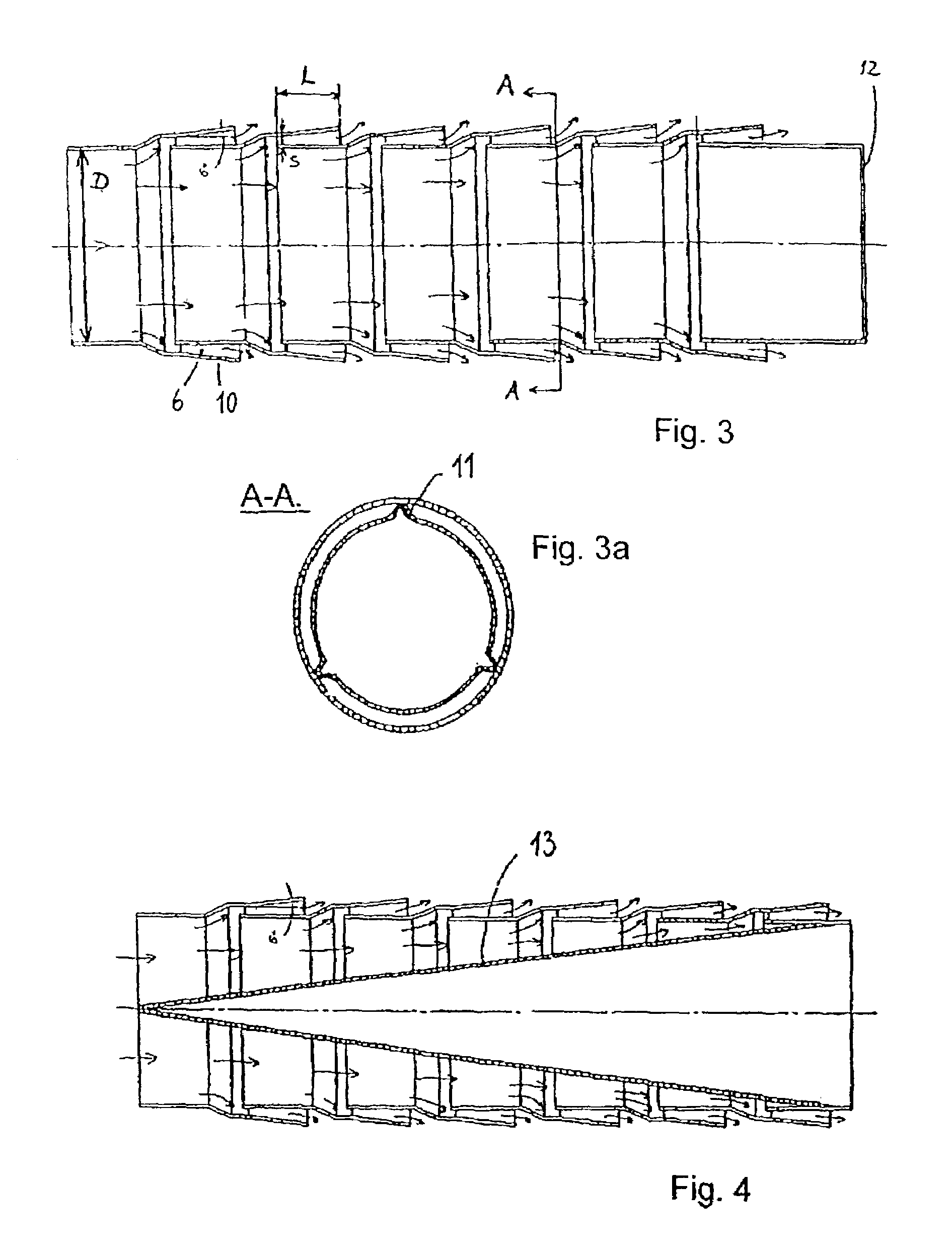
[0011]FIGS. 3 and 3a show the invention.
[0012]FIG. 4 shows a third embodiment of the invention.
[0013]FIG. 5 shows a fourth embodiment of the invention.
[0014]FIG. 6 shows a fifth embodiment of the invention.
[0015]FIG. 7 shows a sixth embodiment of the invention.
[0016]FIG. 8 shows a seventh embodiment of the invention.
[0017]FIG. 9 shows an eighth embodiment of the invention.
[0018]FIG. 10 shows a ninth embodiment of the invention.
Login to View More PUM
 Abstract
A silencer that comprises a casing, one or more pipes or passages leading a flow of gas to the casing and a device for leading gas from the casing. The silencer further has at least one internal chamber, one or more flow inlets to the chamber and one or more flow outlets from the chamber, and one or more flow distributing devices connected to the flow inlet(s) and / or to the flow outlet(s). The flow distributing device comprises one or more walls or profiles extending on a geometrical surface that defines a boundary between an inner volume of the flow distributing device and the chamber. The silencer further has one or more apertures for a flow of gas through the apertures and for leading gas either out of the inner volume into the chamber, or into the inner volume from the chamber. The apertures have a smallest cross-sectional transverse dimension s and a length L, the dimension s being at the maximum 0.2 times the smallest cross-sectional dimension D of the inlet or outlet. The length L is at least the same as the dimension s.
Description
[0001]This application is the national phase under 35 U.S.C. § 371 of PCT International Application No. PCT / DK00 / 00579 which has an International filing date of Oct. 11, 2000, which designated the United States of America.TECHNICAL FIELD[0002]The present invention relates to a silencer, such as a silencer for attenuating the sound level in exhaust gases emerging from a combustion engine.BACKGROUND OF THE INVENTION[0003]Perforated pipes are commonly used in combustion engine exhaust silencers to provide distribution of flow to or from internal silencer chambers and / or to provide acoustic resistance to gas flow through the perforations contributing to overall noise attenuation. Such perforations are normally made as simple holes and create pressure energy losses affecting engine performance adversely.DESCRIPTION OF THE INVENTION[0004]The aim of the present invention is to design silencer flow elements which may replace simple perforated pipe elements in silencers retaining or even imp...
Claims
Login to View More Application Information
Patent Timeline
 IPC IPC(8): F01N1/08F01N1/02F01N7/08F01N1/12F01N13/08
CPCF01N1/08F01N1/12F01N2470/18
InventorFREDERIKSEN, SVENDFREDERIKSEN, LARSMIKKELSEN, SOREN AERENDAL
OwnerSILENTOR HLDG AS