Electrostatic charge-free container

a charge-free, electrostatic technology, applied in the field of containers, can solve the problems of high risk of explosion, high and consequent risk of vapor ignition of the tanks, and achieve the effects of excellent electrical conductivity, good quality, and excellent scratch resistan

Inactive Publication Date: 2007-01-09
GREIF INT HLDG BV
View PDF23 Cites 13 Cited by
  • Summary
  • Abstract
  • Description
  • Claims
  • Application Information

AI Technical Summary

Benefits of technology

[0036]Preferably, the container according to the invention comprises means for creating an effective protection against electrostatic discharges through a continuous electric path between the metallic layer, the metallic cage, the pallet and a ground.
[0060]Lastly, the deposition rate of the metallic material can easily be determined and controlled, from which derives the advantage of being able to define with the maximum precision the final thickness of the metallized layer.

Problems solved by technology

Moreover, it is necessary to foresee the possibility of using the tank in areas where there is a risk of explosion, for example chemical firms or areas intended for varnishing, where substances which can detonate are used and manipulated, even if the material inside the tank is not per se explosive.
The problem is more complex in the case in which such containers are intended to contain and transport materials, in particular materials which are flammable and / or which have a high risk of explosion, and are moved, filled or emptied in explosion risk areas classified under R044-001 in the CENELEC Report (February 1999) Comité Européen de Normalisation Electrotechnique, Brussels.
This can determine the growing up of electrical arcs, with the consequent risk of ignition of the vapors given off by the tanks, of the substances contained in them or of the vapors previously present in the external environment for example in the case of explosion risk areas.
Against the aforementioned advantages the plastic material which the tank is made of, which determines its electrical insulation, is the main cause of the formation of electrostatic discharges or electric arcs.
As a replacement for the coating with conductive varnishes, which has the drawback of not ensuring a sufficiently low resistivity, and of being very degradable and flaky in time, it has been proposed in document EP 674,470 to form a conductive layer sintering metallic powders on the surface of a plastic tank.

Method used


Image

  • Electrostatic charge-free container
  • Electrostatic charge-free container
  • Electrostatic charge-free container

Examples


Embodiment Construction

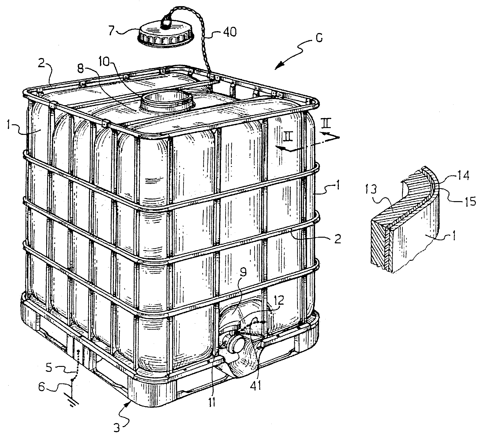
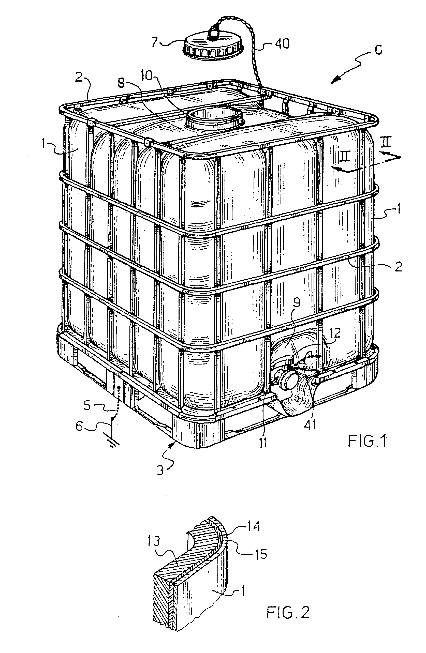
[0067]With reference to the attached figures, with C is generically indicated a container according to the invention for transporting substances, in this specific case a liquid, intended also to be used in high explosion risk environments.

[0068]The container C comprises a tank 1 housed in a metallic cage 2 and supported by a pallet 3, in the example a standard sized pallet.

[0069]The tank 1 is a parallelepiped square with rounded corners and is made of plastic material through the usual extrusion-blowing or rotoforming methods and is then metallized with the method of the present invention according to claim 8.

[0070]The extruded-blown or rotoformed material can, in a preferred embodiment, be high density polyethylene (HDPE) which has the same chemical-physical characteristics as polyethylene but with a greater strength of the final structure of the tank.

[0071]The pallet 3 can be made of metallic material or insulating material, for example wood or plastic. In the example of FIG. 1, t...


PUM


Abstract

Container for the storage and / or transportation of liquids or powders, in particular inflammables, suitable for preventing the formation of electrostatic charge, comprising a tank supported by a pallet, housed in a metallic cage and having an outer surface in contact with said metallic cage. The tank comprises a base layer of plastic material, a layer modified through plasma and a layer of metallic material deposited with vacuum PVD (Physical Vapor Deposition) technique. The metallic layer is in contact with the cage. The metallization of a plastic tank is carried out by generating in a chamber a plasma which activates the outer surface of said tank so as to form a surface layer and carrying out, with vacuum PVD technique, the deposition of a layer of conductive metallic material superposing said surface layer to obtain a tank metallized on the outside.

Description

BACKGROUND OF THE INVENTION[0001]1. Field of the Invention[0002]The present invention refers to a container capable of preventing the formation of electrostatic charge, intended for the storage and / or transportation of liquids or powders, in particular inflammables, and also, but not exclusively capable of being used in environments with a high risk of explosion.[0003]In particular, the invention regards a container for the storage and / or transportation of liquids or powders, in particular inflammables, suitable for preventing the formation of electrostatic charge, comprising a tank externally metallized, supported by a pallet and housed in a metallic cage so as to be in contact with it, as well as the method for carrying out the outer metallization of the tank.[0004]2. Description of the Related Art[0005]As is known, the presence of an outer conductive surface layer allows the rapid draining, towards a means connected to ground, of the possible static electricity which accumulates ...

Claims


Application Information

Patent Timeline
Patent Type & Authority Patents(United States)
IPC IPC(8): B65D85/84B65D19/00B65D25/00B65D65/42B65D77/04B65D77/06
CPCB65D65/42B65D77/0466B65D2213/02
Inventor CASSINA, VIRGINIO
Owner GREIF INT HLDG BV
Why Eureka
Try Eureka