Wide field collimator

a collimator and wide field technology, applied in the field of calibrating optical devices, can solve the problems of large size, high power consumption, and high heat dissipation

Inactive Publication Date: 2007-01-09
NORTHROP GRUMMAN SYST CORP
View PDF24 Cites 32 Cited by
  • Summary
  • Abstract
  • Description
  • Claims
  • Application Information

AI Technical Summary

Benefits of technology

[0015]its size, weight, and power consumption are minimized.It is also desirable to minimize the number of lens elements in the projection lens set, and to minimize the distance between the exit pupil of the lens (the pupil as seen from collimated space) and the front surface of the first lens element. The lens should, of course, provide a satisfactory Modulation Transfer Function (MTF).
[0017]A very high fraction of the light emitted by the LED's is directed through the target plate in the FOV, through the entrance pupil of the projection lens assembly, uniformly filling the pupil but not greatly over-filling it, and into the IUT within a desired spectral band. This efficiency results from the unique interrelationship among the spacings, focal lengths, angles, and other parameters that are described herein. The narrow spectral range of the LED's not only produces high optical efficiency, but also simplifies the design of the projection lens, and of any optical support equipment used to align and test the collimator. Specifically, the projection lens and the autocollimator that is used to align the target plate both contain lenses and have anti-reflection coatings on their refractive elements. The design and fabrication of lenses and of anti-reflection coatings are greatly simplified if they only need to be effective over a narrow spectral range. Since the LED's emit incoherent radiation, coherent interference (speckle) is not a problem. Furthermore, all points on the target plate are illuminated by several LED's.
[0019]Alignment of the target plate in the collimator is handled by providing the target plate with three degrees of freedom of movement. The target is free to translate along the optical axis of the collimator, and is mounted on a gimbal structure so that it may rotate about two axes that are nominally orthogonal to the optical axis of the collimator. This configuration is an advance over the prior art because it enables the use of alignment algorithms that are more time efficient than were possible with a structure that provided axial translation at three points on the target plate.

Problems solved by technology

These collimators have a number of disadvantages, including large size, high power consumption, high heat dissipation, and high cost of operation.
Such a diffusing means has the disadvantage of scattering light at all angles, so it reduces optical efficiency.
This approach is inefficient.
Light that exits the integrating sphere outside the numerical aperture of the condensing lens does not contribute to the useful signal.
The over-all length, mass, and cost of this technique are high.
Tungsten-halogen lamps have very hot surfaces and can explode if these surfaces become contaminated.
The forced-air cooling is a problem itself because fans induce vibration into the optical system and may cause mischief with optical measurements.

Method used


Image

  • Wide field collimator
  • Wide field collimator
  • Wide field collimator

Examples


Embodiment Construction

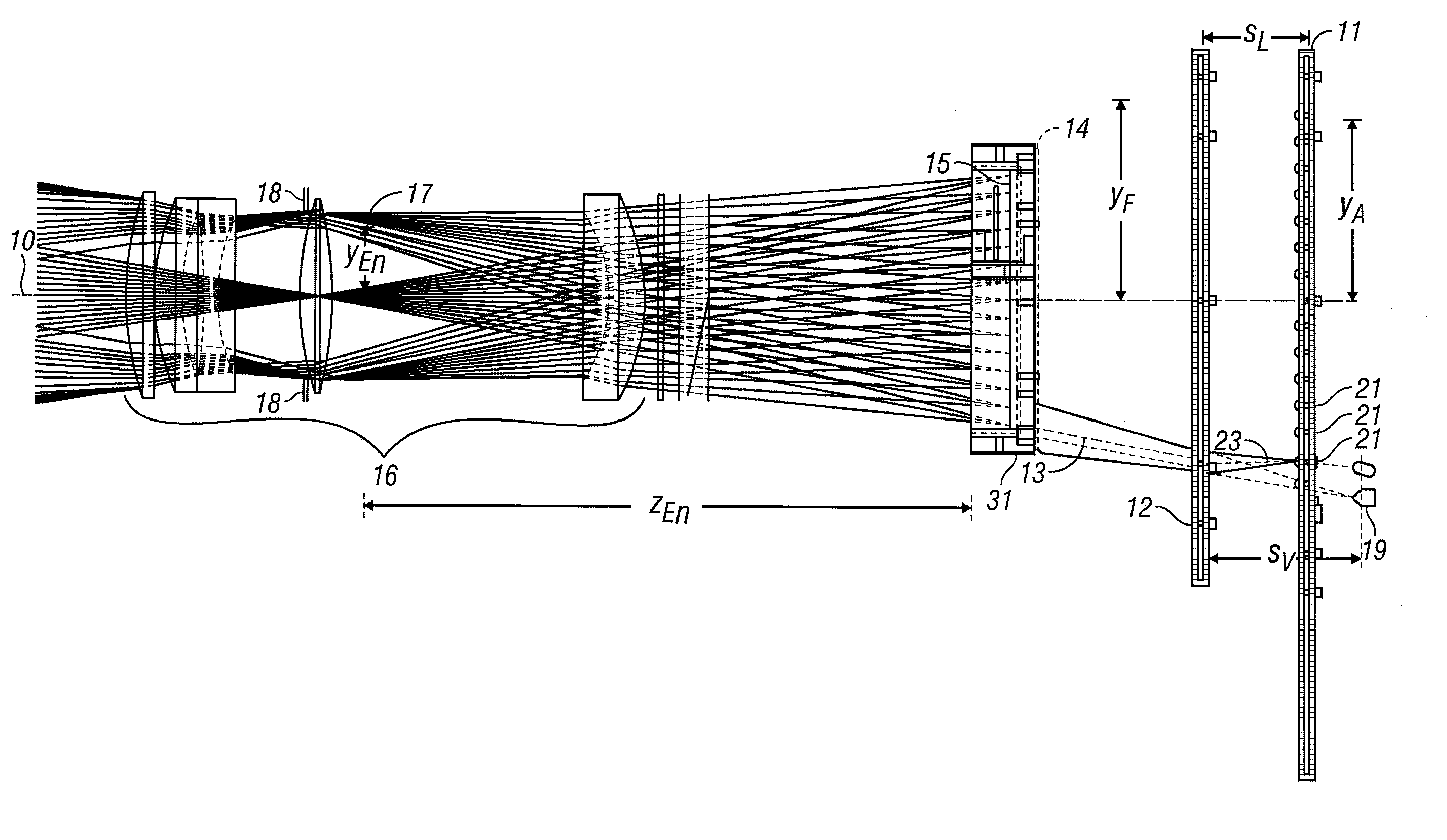
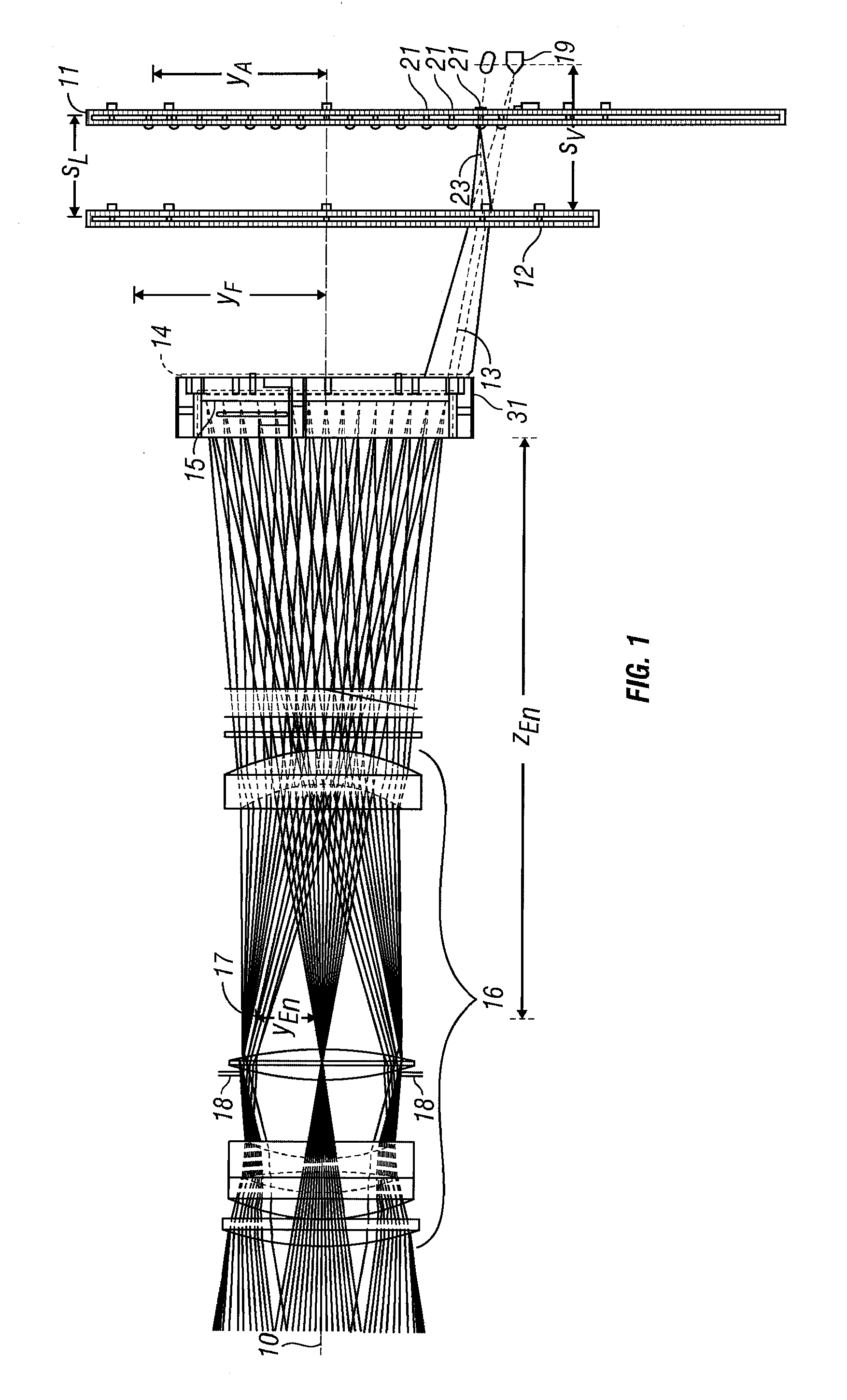
[0027]A collimator embodied according to the present invention projects a test pattern, focused at infinity, over a wide field of view (FOV). This test pattern contains enough optical energy within the bandpass of at least one spectral channel of an instrument under test (IUT) so that a scanning multispectral sensor can be tested with an adequate signal to noise ratio (SNR). Since the collimator is not used for spectral characterization of the IUT, it is not important to match the spectrum of the operational targets of the IUT, only to achieve the necessary brightness within the selected spectral band. Also, the collimator has sufficient acuity in the spectral band to project the test pattern. This acuity is usually quantified in terms of the modulation transfer function (MTF) at one or more critical angular frequencies.

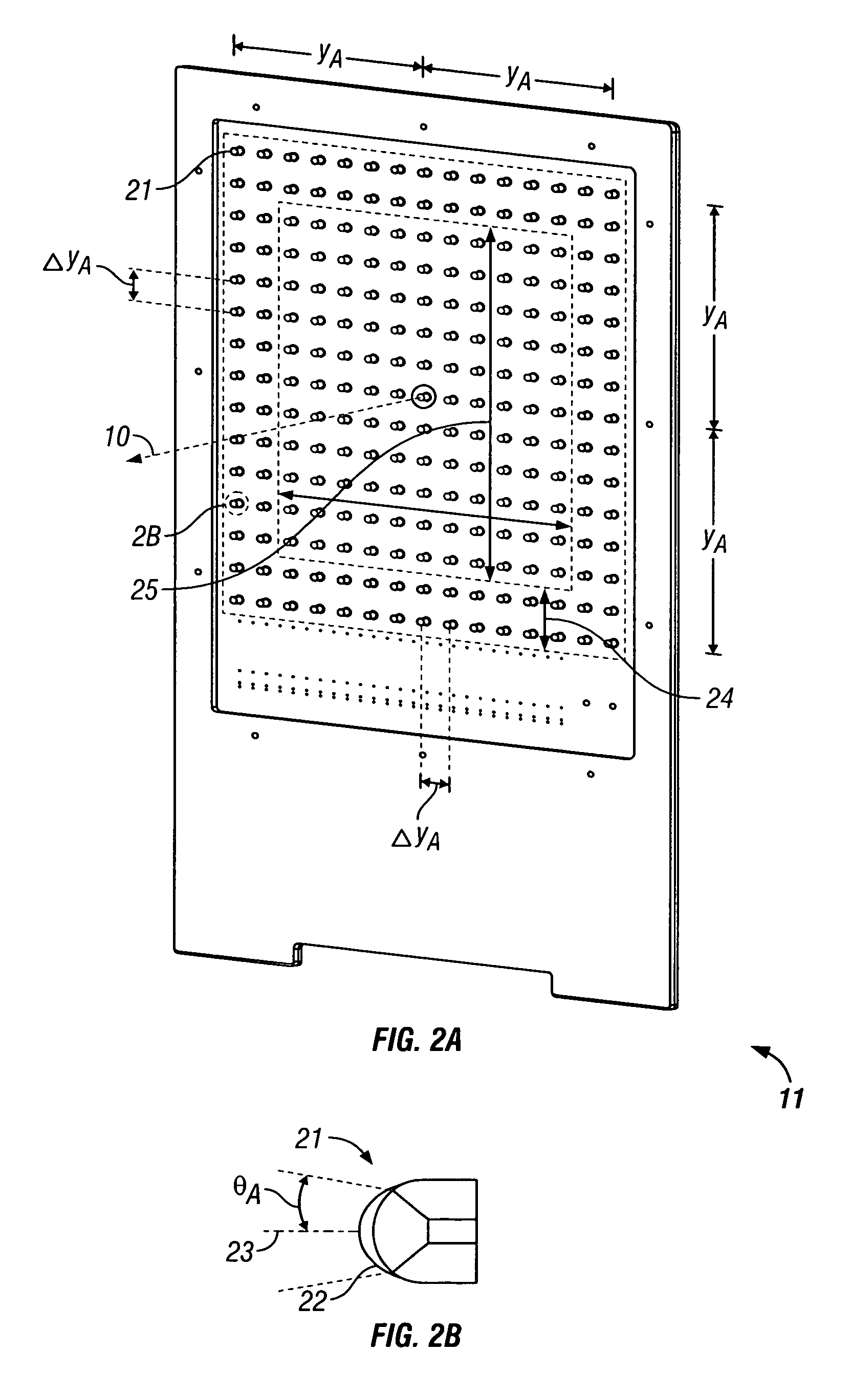
[0028]Salient optical subsystems of the collimator are an illumination source, a condensing lens assembly, a target plate, a projection lens, and a precision alignme...


PUM


Abstract

A collimator is compact and uses power efficient light emitting diodes as the illumination source to generate a test image in collimated space. The collimator provides a test image across a wide field of view, which is useful for calibration of optical devices that have a wide field of regard. An optical projection system in the collimator utilizes an array of light emitting diodes, whose light is converged by a Fresnel lens, through a holographic diffuser plate, onto a target plate bearing the test pattern to be projected out into collimated space through a converging lens. An alignment structure provides translation of the target plate along the main axis of the collimator and provides rotational freedom about two axes (vertical and horizontal) via a gimbal structure mounted on the translation mechanism.

Description

CROSS REFERENCE TO RELATED APPLICATION[0001]This application claims benefit under 35 U.S.C. § 119(e) from provisional application No. 60 / 381,993, filed May 20, 2002. The 60 / 381,993 application is incorporated by reference herein, in its entirety, for all purposes.STATEMENT CONCERNING GOVERNMENT INTEREST[0002]The U.S. Government has a paid-up license in this invention and the right in limited circumstances to require the patent owner to license others on reasonable terms as provided for by the terms of the MSES Contract, Tasks 2113–226, 2113-POl, & 00012.1.0226.00.01, awarded by the National Aeronautics and Space Administration (Goddard Space Flight Center).FIELD OF THE INVENTION[0003]The present invention is generally directed to the field of calibrating optical devices such telescopes and cameras. More particularly, the present invention is directed to projecting a test pattern into the aperture of a scanning, imaging optical instrument so that its dynamic scanning behavior can be ...

Claims


Application Information

Patent Timeline
Patent Type & Authority Patents(United States)
IPC IPC(8): G03B21/26
CPCG03B21/26
Inventor BREMER, JAMES C.PASQUALE, BERT A.ZUKOWSKI, TMITRI J.ZUKOWSKI, BARBARA J.ETEMAD, SHAHRIARPRINCE, ROBERT E.
Owner NORTHROP GRUMMAN SYST CORP
Why Eureka
Try Eureka