Sigmoid notch implant

a sigmoid notch and implant technology, applied in the field of joint prosthesis, can solve the problems of rotational instability, subsequent weakness in grip and pinch, and potential loss of forearm rotation

Active Publication Date: 2007-01-09
MAYO FOUND FOR MEDICAL EDUCATION & RES
View PDF28 Cites 74 Cited by
  • Summary
  • Abstract
  • Description
  • Claims
  • Application Information

AI Technical Summary

Benefits of technology

[0011]The stem of the ulnar head prosthesis is elongated with an extended end for engaging within the intramedullary canal of the resected ulna. The stem of the ulnar head prosthesis also includes a distal end adapted for engagement with the bore in the head of the ulnar prosthesis. The stem further includes a collar between the proximal end of the stem and the distal end of the stem. The collar may be substantially flat. The proximal surface of the collar rests against the resected end of the distal ulna upon implantation to prevent the stem from penetrating excessively into the intramedullary canal of the ulna.

Problems solved by technology

Unfortunately, fractures of the distal radius and other injuries of the forearm commonly occur and may cause rotational instability.
Fracture or dislocation involving the distal radioulnar joint often results in a loss of forearm rotation related to either instability or incongruity between the sigmoid fossa of the distal radius and the head of the ulna.
When there is loss of stability of the distal radioulnar joint, subsequent weakness in grip and pinch as well as potential loss of forearm rotation occur.
Unfortunately, ligament reconstruction of the distal ulna often does not restore complete stability and joint replacement is often performed in an effort to stabilize the joint.
Unfortunately, long term articulation between the man made implant and the natural bone may accelerate wear of the bone and lead to arthritic or degenerative change.
This may cause the patient pain and restriction of motion.
In other circumstances, both the head of the ulna and the distal radius may suffer injury, arthritic change or degenerative change simultaneously.
In addition, in some cases, replacement of the ulnar head with a prosthesis does not fully restore stability to the distal radioulnar joint.
At present, patients that have had an ulnar head resection with implantation of an ulnar head prosthesis who still suffer from instability have few options.

Method used


Image

  • Sigmoid notch implant
  • Sigmoid notch implant
  • Sigmoid notch implant

Examples


Embodiment Construction

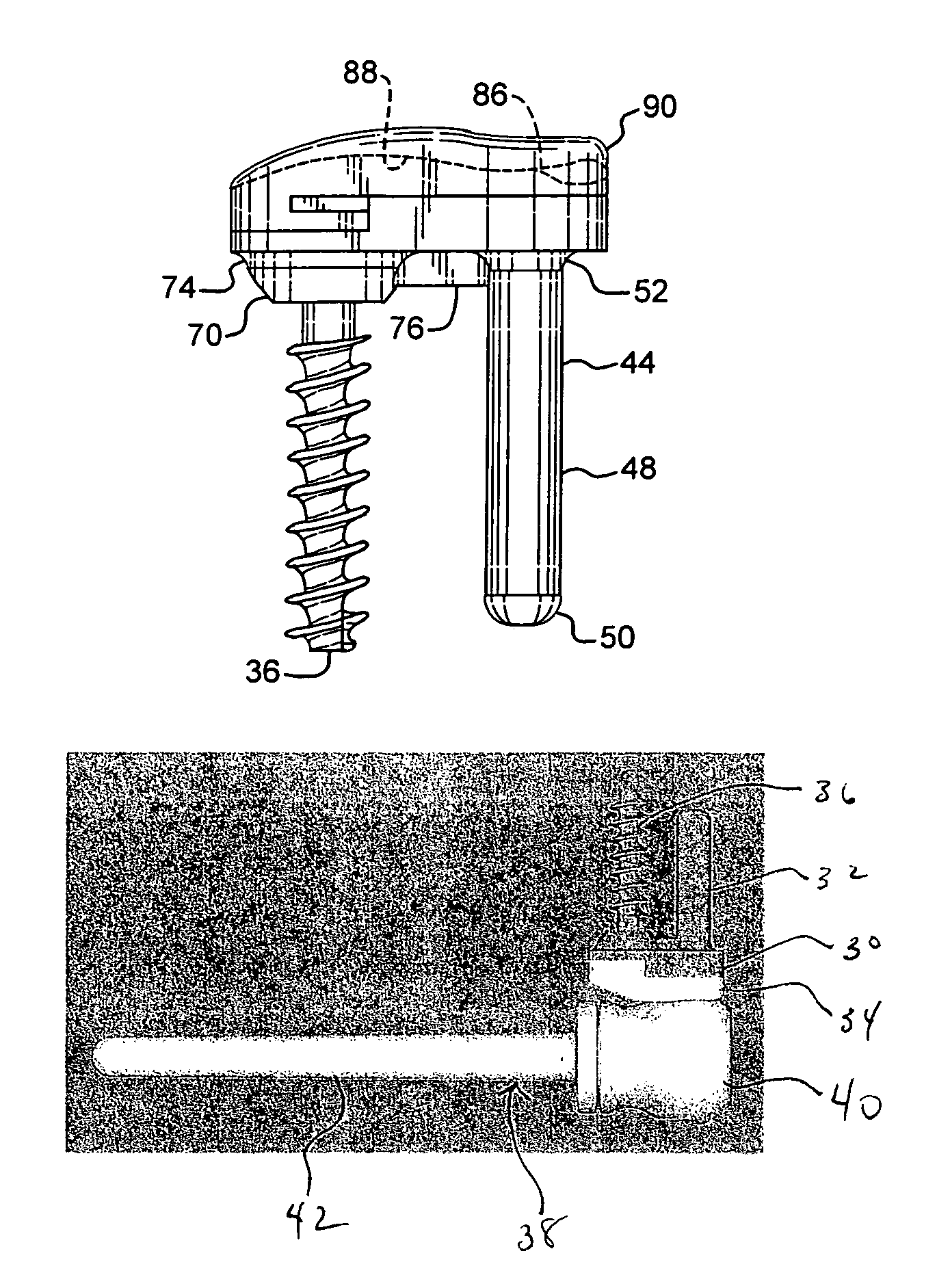
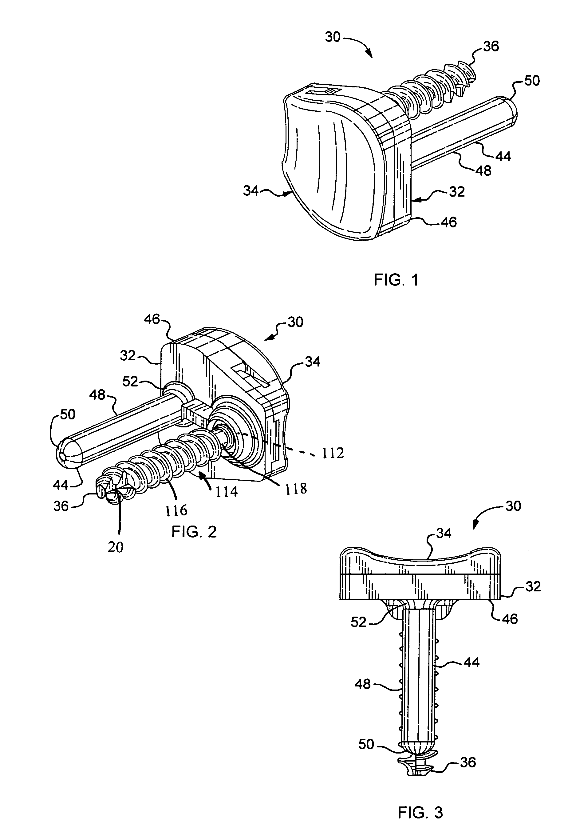
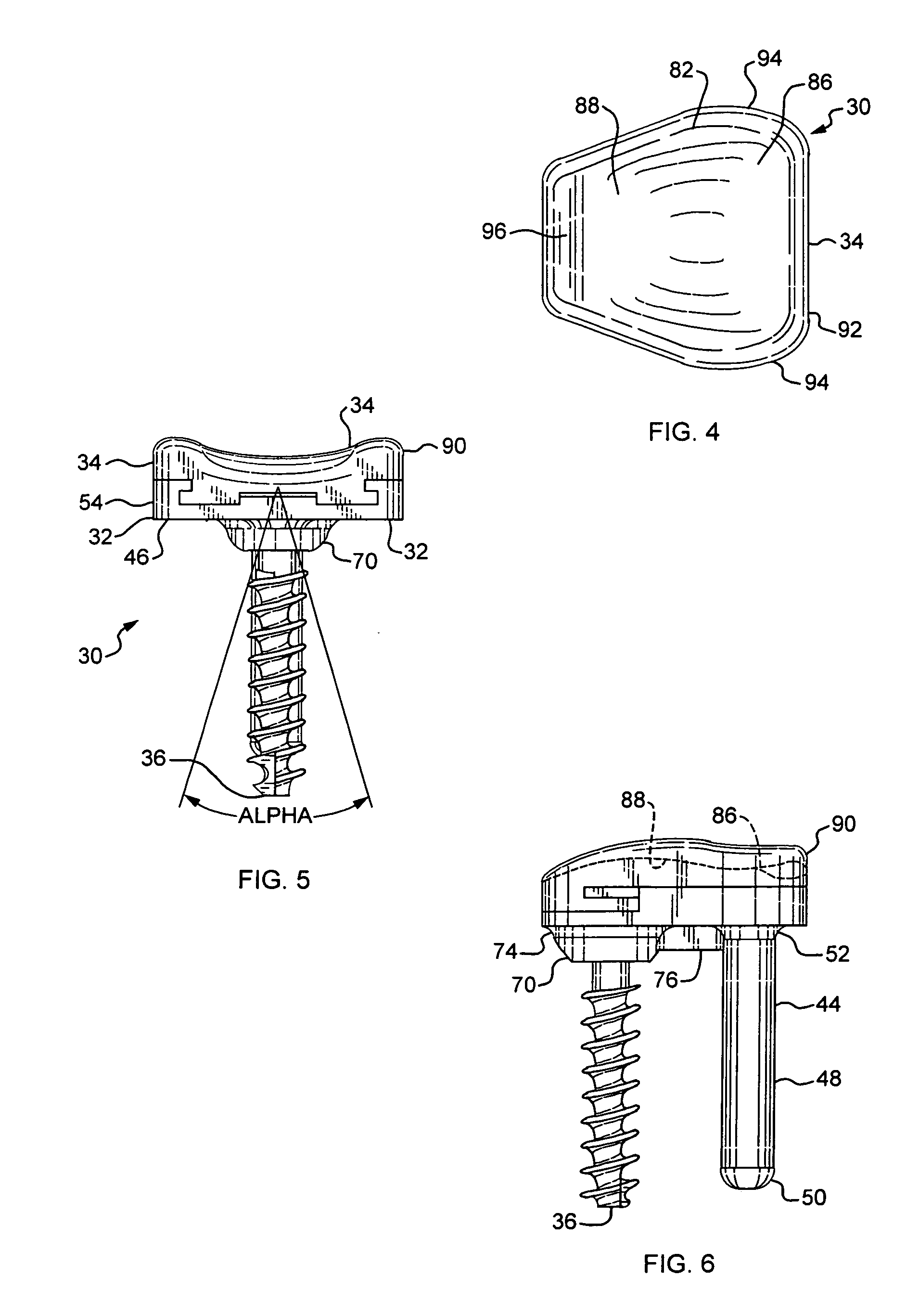
[0036]An embodiment of the sigmoid notch implant 30 generally includes radius portion 32, saddle 34 and bone screw 36. Referring to FIGS. 18 and 19 the sigmoid notch implant 30 is generally utilized along with an ulnar head implant 38. A typical ulnar head implant 38 includes a head portion 40 and a stem portion 42. One exemplary ulnar head prosthesis is disclosed in U.S. Pat. No. 6,302,915. The contents of that U.S. patent are incorporated herein by reference.

[0037]Referring to FIGS. 1–6 and 13–18, radius portion 32 generally includes stem 44 and saddle plate 46. Stem 44 may extend outwardly from saddle plate 46 at a substantially right angle.

[0038]Stem 44 includes cylindrical portion 48 and rounded end 50. Stem 44 joins saddle plate 46 at fillet 52. Stem 44 may also have a tapered shape or include ridges or surface texturing thereon.

[0039]Referring to FIGS. 13–18 saddle plate 46 is roughly trapezoidally shaped and may be integrally formed with stem 44. Saddle plate 46 presents sad...


PUM

PropertyMeasurementUnit
shapeaaaaaaaaaa
radiusaaaaaaaaaa
perimeteraaaaaaaaaa

Abstract

A sigmoid notch resurfacing prosthesis for application to the sigmoid notch of the distal radius. The sigmoid notch prosthesis generally includes a saddle and a radius portion for attachment to the distal radius. The saddle may be formed from ultra high molecular weight polyethylene or another durable self-lubricating material. The saddle includes an at least partially concave contoured depression having rounded edges that is securable to the radius portion. The saddle may be secured by a sliding notch snap fit design. The prosthesis may be adapted for articulation with the natural head of the ulna or with an ulnar head prosthesis that has replaced the ulnar head.

Description

FIELD OF THE INVENTION [0001]The present invention pertains generally to orthopedic prostheses. More particularly, the present invention pertains to a joint prosthesis for the distal radioulnar joint.BACKGROUND OF THE INVENTION [0002]The radius and ulna together form the bony structure of the forearm. The two bones articulate with one another at both their proximal and distal ends. The distal radioulnar joint is a “shallow socket” ball joint. The ulna, a relatively straight bone, translates dorsal-palmarly to accept the modestly bowed radius. The distal end of the radius articulates in pronation and supination on the distal head of the ulna at the sigmoid notch or fossa. The sigmoid notch socket in most wrists is relatively flat and a number of ligaments support the distal ulna where it meets the distal end of the radius. The supporting ligaments include the triangular fibrocartilage (TFC), the extensor carpi ulnaris (ECU) subsheath, and the ulnar collateral ligament complex. The st...

Claims


Application Information

Patent Timeline
Patent Type & Authority Patents(United States)
IPC IPC(8): A61F2/42
CPCA61F2/4684A61F2/4261A61B17/86A61F2310/00407A61F2002/30301A61F2002/30383A61F2002/305A61F2002/30507A61F2002/30604A61F2002/30772A61F2002/3085A61F2002/4269A61F2220/0025A61F2230/0095A61F2310/00017A61F2310/00023
Inventor COONEY, III, WILLIAM P.BERGER, RICHARD A.LEIBEL, DAVID A.
Owner MAYO FOUND FOR MEDICAL EDUCATION & RES
Why Eureka
Try Eureka