Electronic tire management system

a technology of electronic tire management and electronic components, applied in the direction of tyre parts, transportation and packaging, other domestic articles, etc., can solve the problems of inductive magnetic coupling or capacitive coupling, requiring long coil windings, and requiring major modifications in the tire construction and assembly process

Inactive Publication Date: 2007-01-09
BRIDGESTONE AMERICAS TIRE OPERATIONS LLC
View PDF604 Cites 169 Cited by
  • Summary
  • Abstract
  • Description
  • Claims
  • Application Information

AI Technical Summary

Benefits of technology

[0026]Thus, it is an object of the present invention to provide an electronic tire management system that conserves energy.
[0030]It is yet another object of the invention to provide a tire tag that is permanently mounted on a tire for life, enabling a complete tire history to be obtained.

Problems solved by technology

Passive devices that rely on inductive magnetic coupling or capacitive coupling generally have the disadvantage of requiring lengthy coil windings, thus requiring major modifications in the tire construction and assembly process.
Another serious disadvantage with such passive devices is that the interrogator must be positioned in very close proximity to the tire, usually within a few inches of the tire, in order to allow communication between the tire and the device.
Because of the proximity requirements, continuous monitoring is impractical since it would essentially require that an interrogator be mounted at each wheel of the vehicle.
Manual acquisition of the data from the passive devices embedded in each of the tires is also cumbersome and time-consuming because of the proximity requirements.
Externally mounted devices have the disadvantage of being exposed to damage such as from weather and vandalism.
Additionally, externally installed devices can easily become disassociated from a particular tire that is being monitored.
Another disadvantage with known tire monitoring and identification devices is that communication transmissions are achieved using conventional radio frequencies that generally require a relatively large antenna which must be mounted externally or secured to the tire in such a manner that relatively major modifications are required in the tire construction or assembly process.
However, these devices are contained within the tire wheel chamber and have difficulty transmitting data through the tire to external receivers.
Also some additional devices are contained within valve stems that do not attach directly to the tire but, instead, to the wheel or rim so the devices do not provide a permanent record of the tire since the tire could be removed and replaced with another tire on the same rim containing the device.
Also, these prior art devices either attach to the tire, to the wheel, or to the valve stem exclusively and do not provide design flexibility which is desired in many applications.
Also, when using RF frequency communication, difficulties are encountered in transmitting the signals to a remote location due to the problem of transmitting signals through the tire sidewall(s), which, due to tire thickness at this location, materially reduces the transmission efficiency thereof.
It has been observed that the amount of carbon content in the tire affects transmissibility of RF signals thus posing problems for antenna designs.
Further, problems occur with prior art antennae etched into or placed on a substrate or printed circuit board.
Such mounting may increase the difficulty of transmitting signals through the tire sidewalls in the desired direction.

Method used


Image

  • Electronic tire management system
  • Electronic tire management system
  • Electronic tire management system

Examples


Embodiment Construction

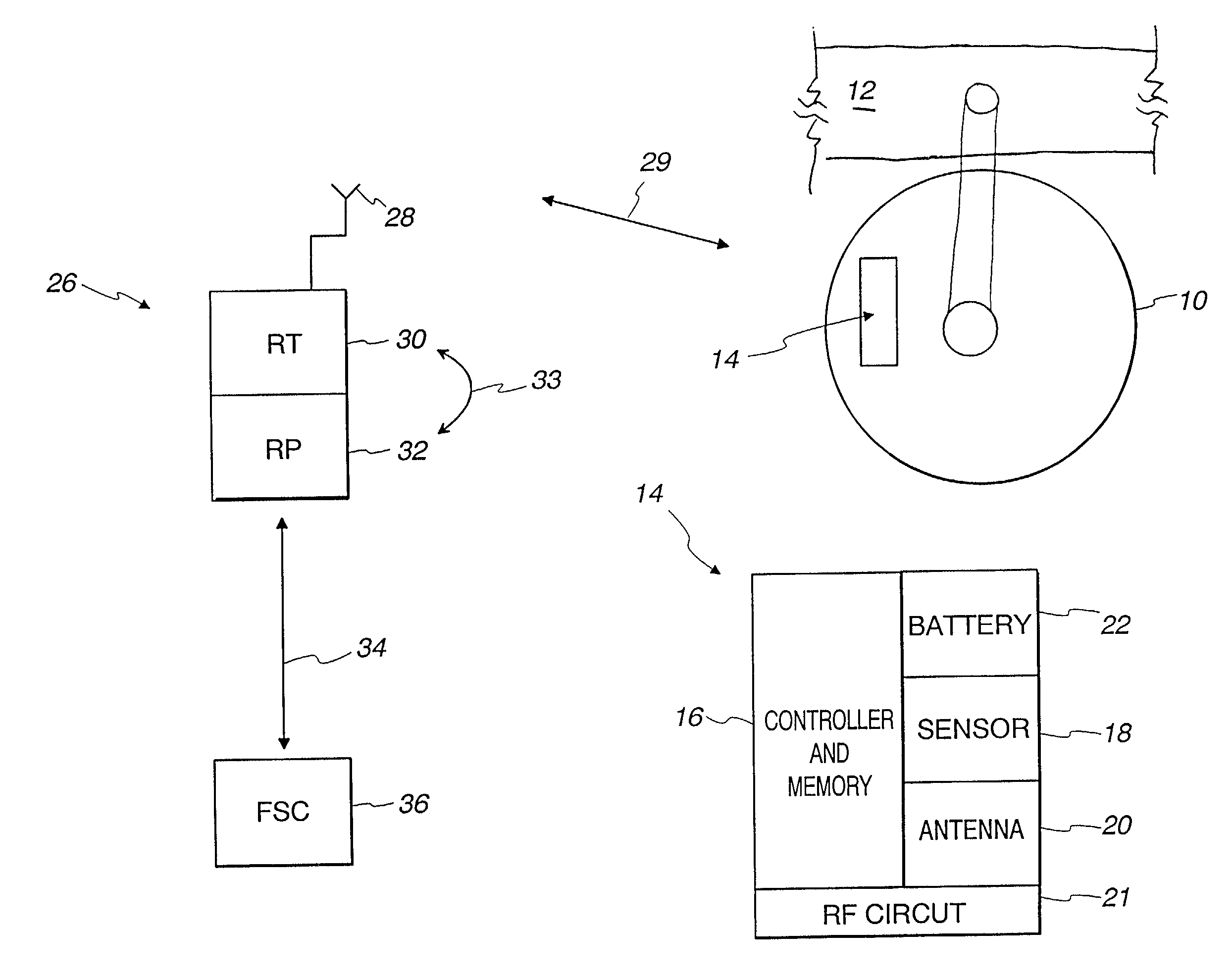
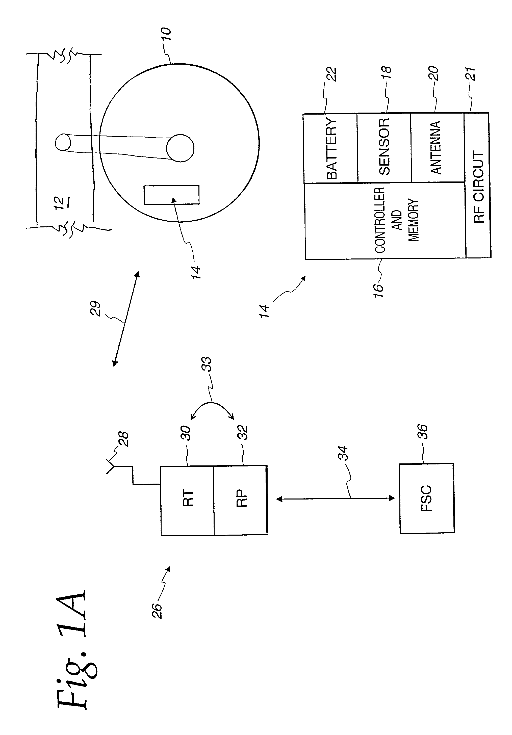
[0076]Illustrated in FIG. 1A is a block diagram of one embodiment of the Electronic Tire Management System (ETMS). A tire tag 14 is located within a tire 10 mounted on a vehicle 12. Various methods of attaching the tire tag 14 to the interior of the tire 10 have been described in various patents and related applications, including U.S. Pat. No. 5,500,065 entitled “Method for Embedding a Monitoring Device Within a Tire During Manufacture”; U.S. Pat. No. 5,562,787 entitled “Method of Monitoring Conditions of Vehicle Tires”; U.S. Pat. No.5,573,610 entitled “Tires Containing a Monitoring Device for Monitoring an Engineering Condition Therein”; U.S. Pat. No. 5,573,611 entitled “Method of Monitoring Conditions of Vehicle Tires and Tires Containing a Monitoring Device Therein”; and U.S. Pat. No. 5,971,046, filed Sep. 17, 1997, and entitled “Method and Apparatus for Bonding an Active Tag to a Patch and a Tire”; all commonly assigned to the assignee of the present invention and all of which ...


PUM


Abstract

An electronic tire maintenance system is provided for measuring a parameter of a device at a first location. The system includes a sensor for measuring the device parameter and generating a data signal representing the measured parameter. The system also includes a microprocessor coupled to the sensor for activating the sensor on a first periodic basis to measure the device parameter. The microprocessor includes a memory for storing the generated data signal representing the measured parameter. A transmitter and a receiver are coupled to the microprocessor. The microprocessor periodically partially awakens to determine, on a second periodic basis, if a received transmission is a valid interrogation signal and, if so, fully awakens and responds to the valid interrogation signal, via the transmitter, by at least transmitting the last stored measured parameter. In one embodiment, the device is a tire tag mounted inside a tire that measures tire data and transmits that data to a remote source in response to an interrogation request, an alert condition, or automatically on a periodic basis.

Description

CROSS-REFERENCE TO RELATED APPLICATIONS[0001]This application is a continuation-in-part (CIP) of U.S. application Ser. No. 09 / 915,858, filed Jul. 26, 2001 now U.S. Pat. No. 6,630,885, which claims priority to and the benefit of U.S. Provisional Application Ser. No. 60 / 220,896, filed Jul. 26, 2000. The applicants are claiming priority to and the benefit of both of these applications, making the effective filing date of all common subject matter in this application Jul. 26, 2000. Each of the above related applications are assigned to the assignee of the present application.FIELD OF THE INVENTION[0002]The present invention relates in general to tire parameter monitoring systems and in particular to an electronic tire management system including tire tags, where each tag has an electronic sensor circuit that conserves power by “sleeping” and periodically “waking-up” to measure and store tire parameters, such as temperature and pressure. The tag microprocessor periodically awakens to a s...

Claims


Application Information

Patent Timeline
Patent Type & Authority Patents(United States)
IPC IPC(8): B60C23/00B60C23/04
CPCB60C23/0433B60C23/0493B60C23/0452B60C23/0444B29D2030/0072B60C23/0442B60C23/0462B60C23/0479
Inventor HARDMAN, GORDON E.PYNE, JOHN W.HARDMAN, MOLLY A.PRZYGOCKI, DAVID A.COOMBS, DAVID M.WILSON, PAUL B.GRUSH, RONALD C.LOUDIN, PHILIP B.FLOYD, BRETT W.
Owner BRIDGESTONE AMERICAS TIRE OPERATIONS LLC
Why Eureka
Try Eureka