
Material identification employing a grating spectrometer

a grating spectrometer and material technology, applied in the direction of spectrometry/spectrophotometry/monochromators, instruments, optical radiation measurement, etc., can solve the problem of difficult deciphering of the spectrum, the frequency of filter change and the use of band pass filters, and the low efficiency of the diffraction grating near the end of the rang

Inactive Publication Date: 2007-01-09
UNIV OF FLORIDA RES FOUNDATION INC
View PDF11 Cites 41 Cited by
  • Summary
  • Abstract
  • Description
  • Claims
  • Application Information

AI Technical Summary

Benefits of technology

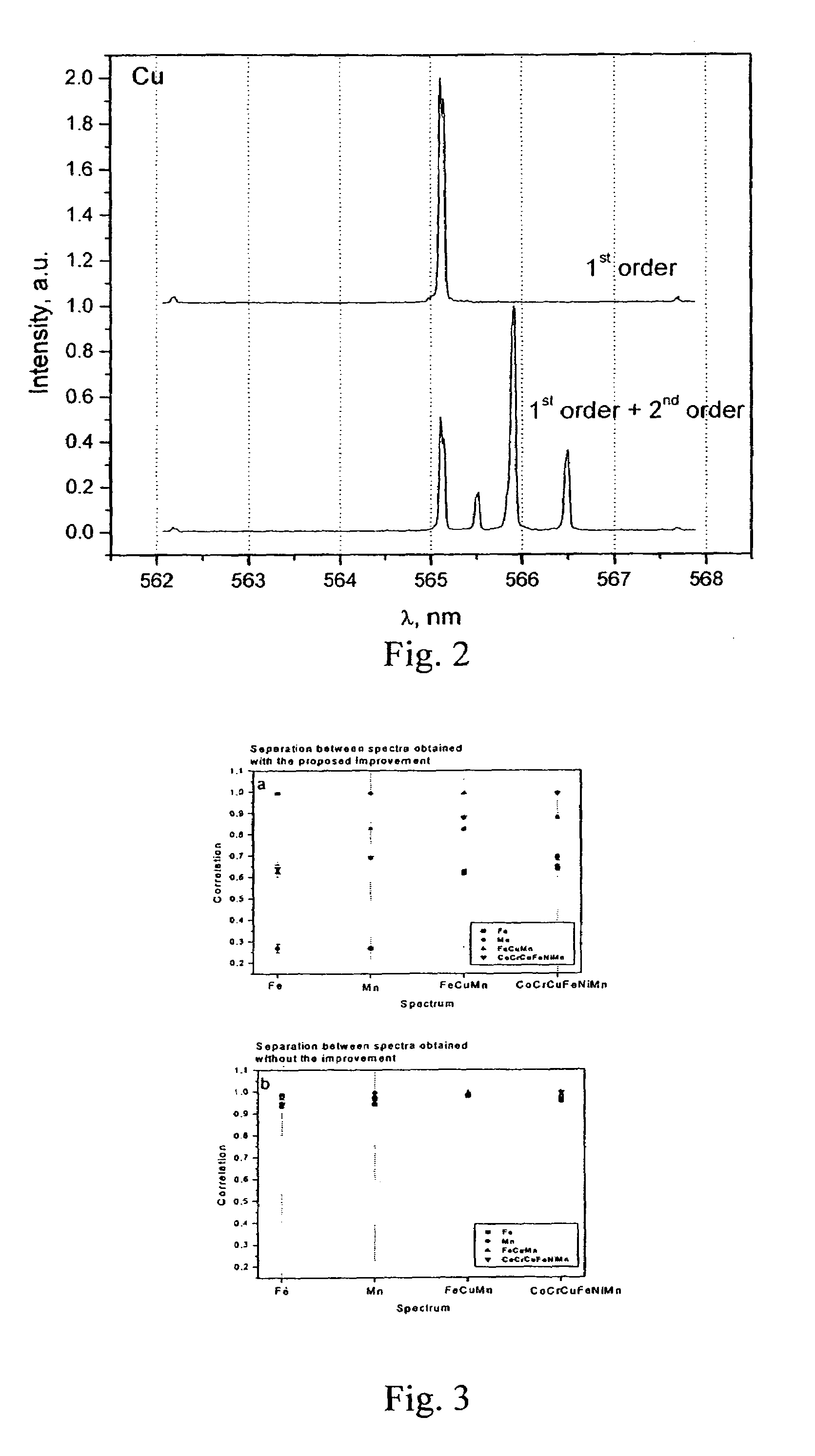
[0019]Thus, in conventional spectroscopy, order overlap is considered undesirable. However, in the identification methodology and system of the present invention, based on correlation analysis, such overlap is beneficial because there is no need to assign spectral features. The spectrum is used as a fixed piece of information without detailing its content. Multiple order spectra provide more simultaneous useful information for the correlation process. Of course, this occurs at the expense of a partial loss in the spectral resolution (if lines from different orders overlap), but this effect is overshadowed by the inherent benefits for correlation analysis and its application to reliable material identification.
[0021]The exemplary methodology and system of the invention may also be employed successfully utilizing Echelle grating spectrometers. The Echelle spectrometer is designed to work in a multi-order regime. A cross dispersion element (a prism) is used in Echelle spectrometers as an order sorter. However, no cross dispersion element is required for the reliable correlation analysis achievable with the system of the invention. Thus, cheap and simple Echelle grating spectrometers may be employed for material identification.

Problems solved by technology

Another exemplary disadvantage of a diffraction grating, which is used in the first grating order through a large wavelength range, is the low efficiency of the diffraction grating near the ends of the range.
This requires, however, a more frequent filter change and the use of band pass filters.
If two or more orders are displayed simultaneously, the deciphering of the spectrum becomes problematic.
Thus, in conventional spectroscopy, order overlap is considered undesirable.

Method used


Image

  • Material identification employing a grating spectrometer
  • Material identification employing a grating spectrometer
  • Material identification employing a grating spectrometer

Examples


Embodiment Construction

[0027]The exemplary systems and methods of this invention will be described in relation to a spectroscopy system and methodology. However, to avoid unnecessarily obscuring the present invention, the following description omits well-known structures and devices that may be shown in block diagram form or otherwise summarized. For the purpose of explanation, numerous specific details are set forth in order to provide a thorough understanding of the present invention. It should be appreciated, however, that the present invention may be practiced in a variety of ways beyond the specific details set forth herein. For example, any type of spectroscopic technique and equipment can be used to obtain the spectral data as discussed herein.

[0028]Furthermore, while the exemplary embodiments illustrated herein show the various components of the spectroscopy system collocated, it is to be appreciated that the various components of the system can be located at distant portions of a distributed netw...


PUM

PropertyMeasurementUnit
wavelengthaaaaaaaaaa

Abstract

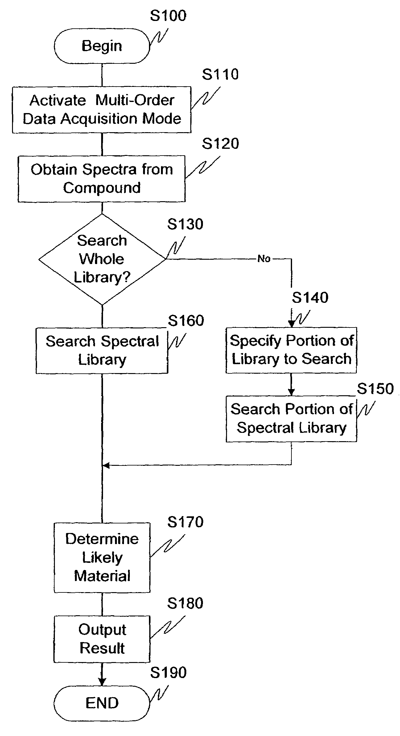
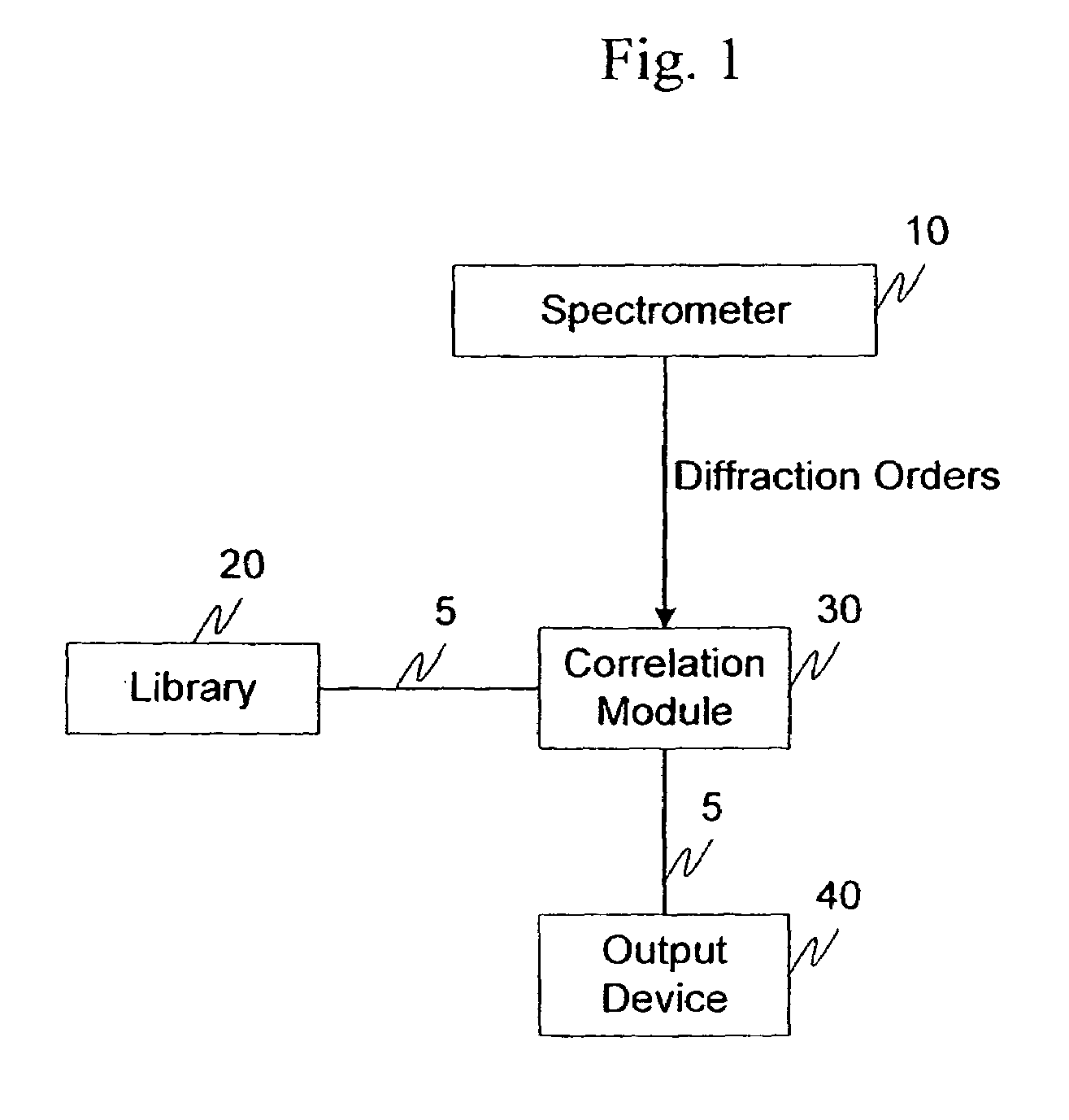
Multi-ordered spectral data is obtained from various known substances and is stored in a spectral library. The identification of an unknown material is accomplished by correlating the sample's multi-ordered spectrum against all or a portion of the spectrum in the library, and finding the closest match.

Description

RELATED APPLICATION DATA[0001]This application claims the benefit of and priority under 35 U.S.C. §119(e) to U.S. patent application Ser. No. 60 / 453,968, filed Mar. 13, 2003, entitled “Method of Material Identification Employing Grating Spectrometer” which is incorporated herein by reference in its entirety.GOVERNMENT INTERESTS[0002]This study was support by the U.S. Department of Energy, Contract No. DEFG02-99ER 14960.BACKGROUND[0003]1. Field of the Invention[0004]The invention generally relates to methods and systems for the identification of unknown materials employing spectral information associated with the material.[0005]2. Description of Related Art[0006]The reliable identification of unknown materials relies upon the amount of information that can be obtained from measurements of physical or chemical characteristics of the material. One such identification methodology uses spectral information. Each material is characterized by its own unique spectral fingerprint. The spectr...

Claims


Application Information

Patent Timeline
Patent Type & Authority Patents(United States)
IPC IPC(8): G01J3/28G01N21/31
CPCG01N21/31
Inventor GORNUSHKIN, IGNOR B.WINEFORDNER, JAMES D.SMITH, BENJAMIN W.
Owner UNIV OF FLORIDA RES FOUNDATION INC
Learn More