Method and system for assessing life of cracked dovetail in turbine

a technology of cracking and dovetails, applied in the field of steam turbines, can solve the problems of high stress on the dovetail connection between the bucket and the wheel, failure of the wheel hook, and easy wear and cracking of the dovetail

Active Publication Date: 2007-01-09
GENERAL ELECTRIC CO
View PDF14 Cites 71 Cited by
  • Summary
  • Abstract
  • Description
  • Claims
  • Application Information

AI Technical Summary

Benefits of technology

[0010]There is a long felt need for an analytical tool to evaluate the impact that SCC will have on the useful life of a turbine rotor. It would be helpful to have such a tool when determining whether to return a turbine to service, or repair or replace the dovetail connectors on the wheels.

Problems solved by technology

A common difficulty with all types of dovetail configurations is that the dovetail connections between the buckets and wheels are highly stressed and, after years of operation, tend to wear out and crack.
Normally, these stresses are acceptable but with contaminated steam and age, cracks can initiate and, if left undetected, may grow to a depth that will cause failure of the wheel hooks.
Moreover, the steam at the low-pressure end of the turbine, contaminated or otherwise, is at a lower temperature having been cooled during passage through the turbine.
Because of the mass and the rotational speed of a turbine, e.g., typically on the order of 3,600 revolutions per minute (rpm), significant damage to the turbine, its housing and surrounds, as well as injury to turbine operators, can occur should cracks develop in the wheel dovetail sufficiently to permit one or more of the buckets to fly off the rotor wheel.
In extreme cases, all the hooks will fail and buckets will fly loose from the rotor.
The low-pressure (LP) sections of nuclear and fossil fuel driven steam turbines are especially susceptible to SCC.

Method used


Image

  • Method and system for assessing life of cracked dovetail in turbine
  • Method and system for assessing life of cracked dovetail in turbine
  • Method and system for assessing life of cracked dovetail in turbine

Examples


Embodiment Construction

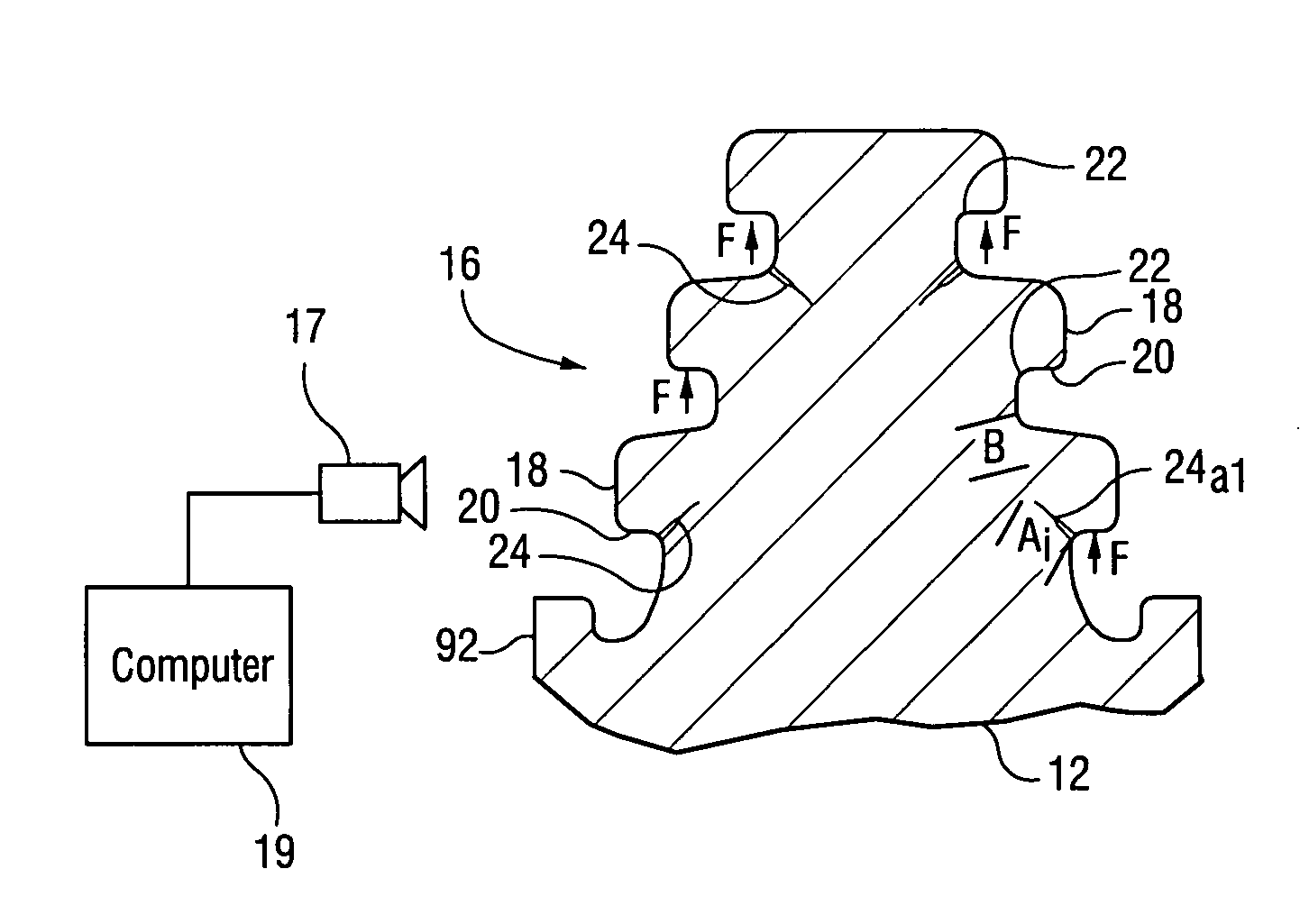
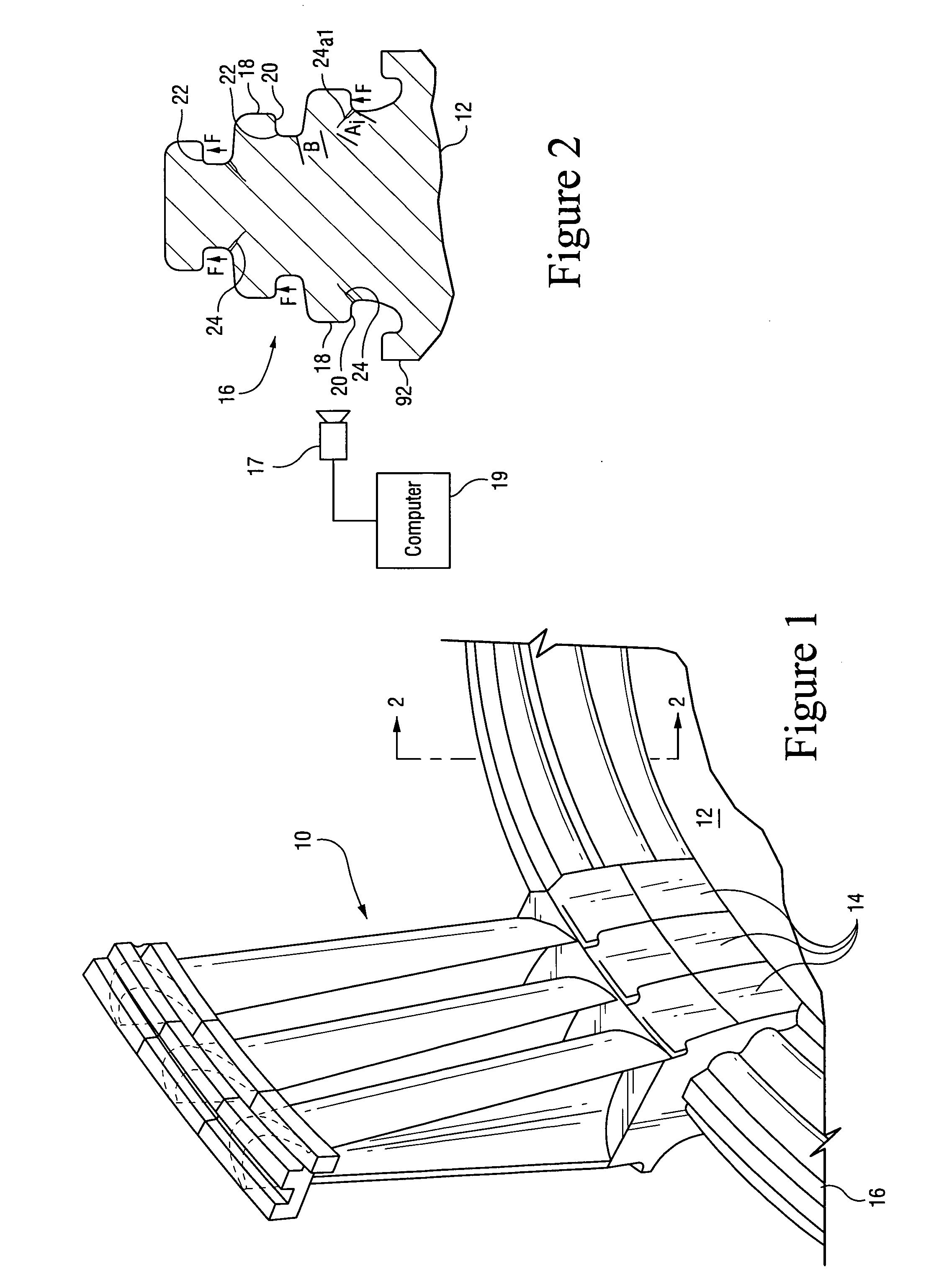
[0019]FIG. 2 is a cross-sectional diagram of a tangential dovetail connector 16 for a turbine wheel 12. The dovetail connector is at the outer circular rim of the wheel. The connector generally comprises a inverted “V” shape having a series of ridges 18 extending outwardly from the sides of the connector. These ridges 18 are generally referred to as “hooks” of the connector. The hooks provide an attachment for the matching dovetail 14 at the base of each turbine bucket 10.

[0020]The hooks 18 of the dovetail connector are generally loaded along their underside surfaces 20. The loading occurs as the matching hooks of the dovetail connector of the turbine bucket abut against the underside surfaces 20 of the dovetail connector on the wheel 12. During rotation of the wheel, centrifugal forces act in a radial direction. The centrifugal forces apply radial forces (F) to the underside surfaces 20 on the dovetail connector 16 of the wheel. These forces are proportional to the rotational speed...


PUM


Abstract

A method has been developed for predicting a remaining operational life of a turbine component including: obtaining crack flaw data regarding current crack flaws in the turbine component; using the crack flaw data with data regarding the structure and operating conditions of the turbine component to determine force loads applied to the turbine component and generate crack propagation data; applying a probalistic analysis to the crack flaw data and the generated crack propagation data to generate a statistical distribution of crack data, and applying the statistical distribution of crack data to predict a time to failure of the component by iteratively determining the force loads for successive periods of time.

Description

BACKGROUND OF THE INVENTION[0001]This disclosure generally relates to steam turbines. More particularly, this disclosure relates to methods for assessing cracking of turbine rotors and other metal turbine components exposed to water, steam and condensate in the steam turbine.[0002]Steam turbine power systems use a fluid medium such as water or another suitable chemical fluid with boiling points and latent heat values appropriate for the operational temperatures of the system. The fluid medium is generally heated in a separate heat source such as a boiler by using directed solar radiation, burning of fossil fuel, nuclear radiation or geothermal energy. The energy is transferred from the heat source to a turbine(s) in the form of high-pressure steam that powers the turbines. The steam turns a rotor in the turbine. The rotation of the turbine may be applied to drive an electromagnetic generator producing electricity.[0003]A common type of steam turbine system includes a plurality of tu...

Claims


Application Information

Patent Timeline
Patent Type & Authority Patents(United States)
IPC IPC(8): G01B5/30G01M99/00
CPCF01D21/003G01N29/041G01N29/045G01N29/4418G01N2203/0062G01N2203/0073F05D2260/80G01N2291/0235G01N2291/0258G01N2291/02827G01N2291/0422G01N2291/2693G01N2203/0075
Inventor KADIOGLU, YAVUZGUPTA, ANIL KUMARNAIR, RAVICHANDRAN PAZHUREKLAND, ERIC JOSEPHEMETERIO, ELOY VINCENT
Owner GENERAL ELECTRIC CO
Why Eureka
Try Eureka