Exhaust gas turbocharger for an internal combustion engine

a technology of exhaust gas and turbocharger, which is applied in the direction of positive displacement liquid engines, liquid fuel engines, pipe pumps, etc., can solve the problems of inability to achieve other functions and relatively high construction expenditures for auxiliary compressors, and achieve the effect of simple construction means

Inactive Publication Date: 2007-01-16
DAIMLER AG
View PDF19 Cites 18 Cited by
  • Summary
  • Abstract
  • Description
  • Claims
  • Application Information

AI Technical Summary

Benefits of technology

[0011]The pumping function can be improved by providing in the exhaust gas bypass, a nozzle area with reduced flow cross-section and the gas pumping line joins the bypass line in the area of the smallest flow cross-section. As the pressure in the gas flow drops as it flows with increased speed through the reduced flow cross-section area the pressure of the exhaust gas is further reduced, which provides for an increased pumping effect in the gas pumping arrangement.
[0013]The bypass line extends preferably annularly around the turbine wheel wherein a plurality of ejector components are arranged distributed over the circumference and between adjacent ejector components a narrow nozzle cross-section is formed. The ejector components may be of the same kind, particularly identical or mirror symmetrical. In accordance with another embodiment, they may differ in design such that the nozzle inlet cross-section disposed between two adjacent ejectors and the nozzle discharge cross-section provide for different flow directions for the gas flowing therethrough. In this way, additional flow effects can be obtained.
[0014]In the ejector component, there is expediently a discharge channel for the gas pumping line wherein the discharge channel extends about normal to the direction of the exhaust gas flow in the bypass line. This embodiment provides for a simple connection of the gas pumping line to the ejector component. The discharge channel is connected to the bypass line by way of the discharge opening wherein the discharge opening may have the shape of a slot and be oriented essentially parallel to the orientation of the nozzle discharge cross-section, so that the gas entering the bypass line has essentially the same flow direction as the exhaust gas flowing through the bypass line. In this way, the suction effect provided by the exhaust gas flow is improved.

Problems solved by technology

However, the additional auxiliary compressor requires relatively high construction expenditures.
Other functions cannot be accomplished.

Method used


Image

  • Exhaust gas turbocharger for an internal combustion engine
  • Exhaust gas turbocharger for an internal combustion engine
  • Exhaust gas turbocharger for an internal combustion engine

Examples


Embodiment Construction

[0023]In the various figures, identical components are designated by the same reference minerals.

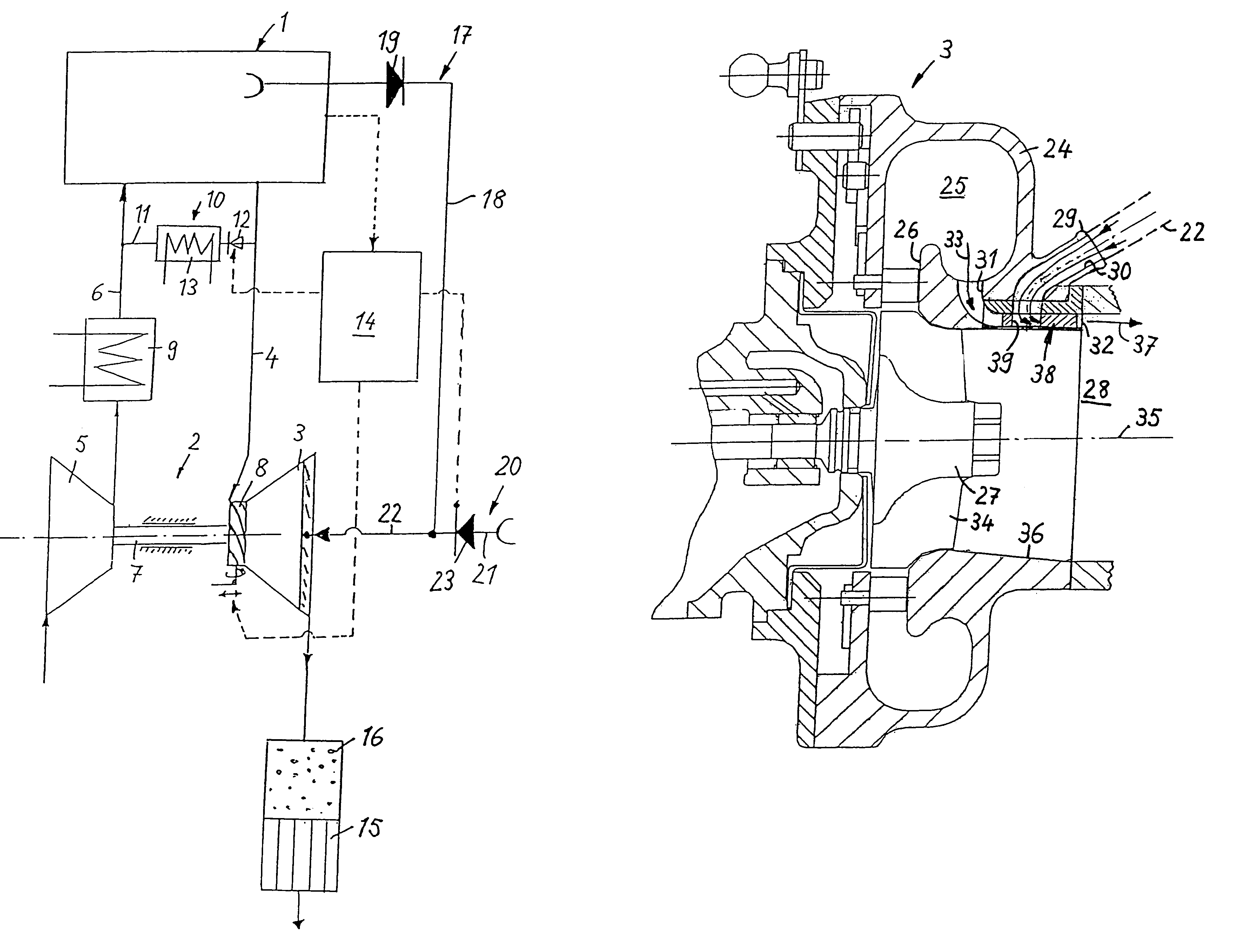
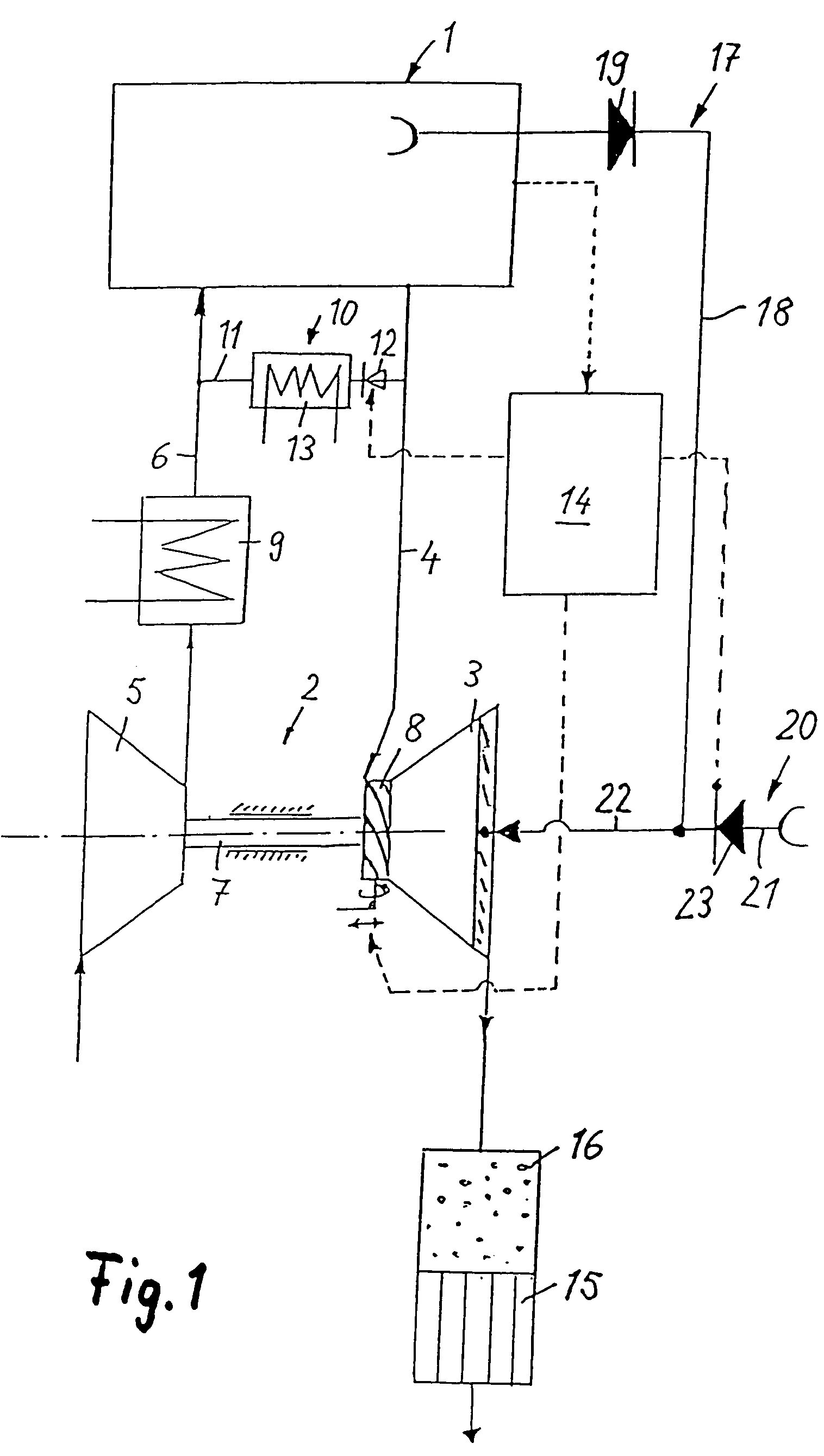
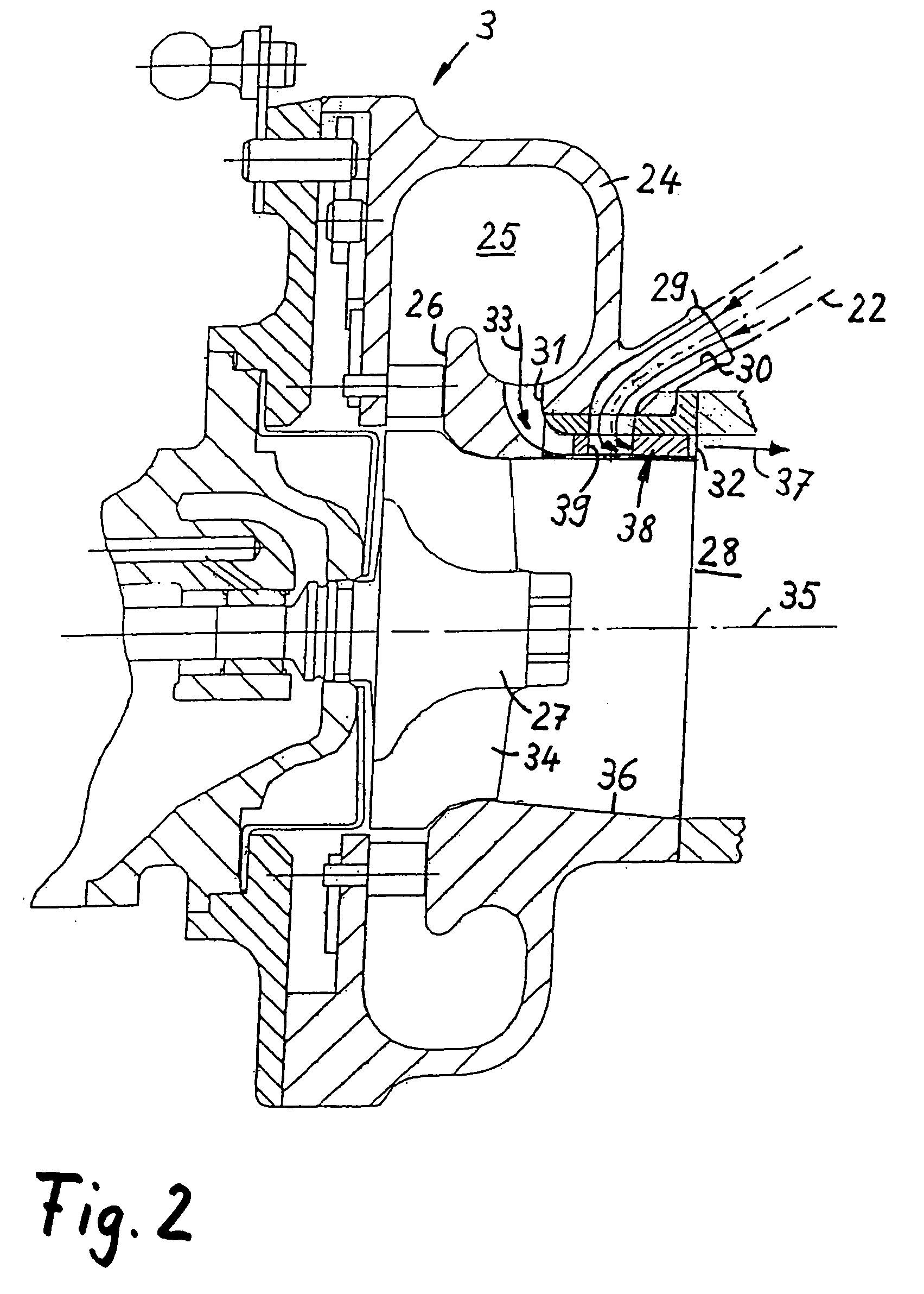
[0024]The internal combustion engine 1 which is shown in FIG. 1 and which may be a gasoline engine or a diesel engine includes an exhaust gas turbocharger 2 with an exhaust gas turbine 3 in the exhaust duct 4 and a compressor 5 in the intake duct 6. The exhaust gas turbine 3 is driven by the exhaust gases of the internal combustion engine which are still under a certain pressure. The compressor 5 is driven by the exhaust gas turbine 3 via a shaft and takes in ambient air and compresses it to an increased charge air pressure. The exhaust gas turbine 3 includes a variable turbine inlet vane structure 8 for controlling the effective turbine inlet flow passage. Downstream of the compressor 5, the intake duct 6 includes a charge air cooler 9 in which the air compressed in the compressor 5 is cooled. Downstream of the charge air cooler 9, the pressurized charge air is supplied to the cylinder ...


PUM


Abstract

In an exhaust gas turbocharger of an internal combustion engine including a compressor arranged in the intake duct and a turbine arranged in the exhaust duct of the engine, wherein the turbine includes in its housing an exhaust collection chamber from which the exhaust gas is directed via turbine inlet passage to the turbine wheel, the housing also includes a bypass arrangement for conducting part of the exhaust gas to the turbine exhaust structure in a turbine wheel bypass line which includes an ejector structure forming a gas pumping device.

Description

[0001]This is a Continuation-In-Part Application of International Application PCT / EP03 / 13071 filed Nov. 21, 2003 and claiming the priority of German application 102 60 778.8 filed Dec. 13, 2002.BACKGROUND OF THE INVENTION[0002]The invention relates to an exhaust gas turbocharger for an internal combustion engine including a compressor arranged in the intake duct and an exhaust gas turbine arranged in the exhaust duct of the engine in a turbine housing having an exhaust gas collection chamber from which the exhaust gas is directed onto the turbine wheel via a turbine inlet passage and a bypass arrangement for bypassing the turbine inlet passages.[0003]DE 43 12 078 A1 discloses a turbocharged internal combustion engine with an exhaust gas turbine in the exhaust duct and a compressor in the intake duct of the internal combustion engine. By the compressor, the combustion air is compressed to an increased charge pressure with which the air is supplied to the cylinders of the engine. The ...

Claims


Application Information

Patent Timeline
Patent Type & Authority Patents(United States)
IPC IPC(8): F02D23/00F02B37/00F02B37/12F01N3/035F01N3/22F01N3/30F02B29/04F02B37/18F02B37/24F02M25/07
CPCF01N3/035F01N3/22F01N3/222F01N3/225F01N3/30F02B37/24F02M25/0707F02M25/0713F02B37/18F02B29/0406Y02T10/144F02M25/0727Y02T10/121F02M26/05F02M26/10F02M26/23Y02T10/12
Inventor SCHMID, WOLFRAMSUMSER, SIEFRIED
Owner DAIMLER AG
Why Eureka
Try Eureka